High beam and motor vehicle
A high-beam and low-beam technology, applied in the direction of motor vehicles, headlights, road vehicles, etc., can solve the driver's eye damage, traffic accidents and other problems, to reduce the probability of driving accidents, reduce injuries, and eliminate glare Effect
- Summary
- Abstract
- Description
- Claims
- Application Information
AI Technical Summary
Problems solved by technology
Method used
Image
Examples
Embodiment 1
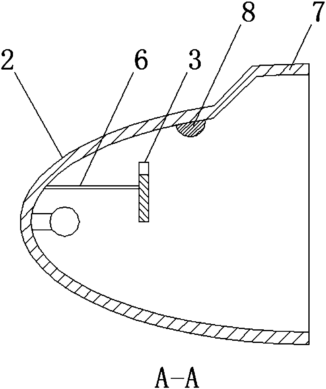
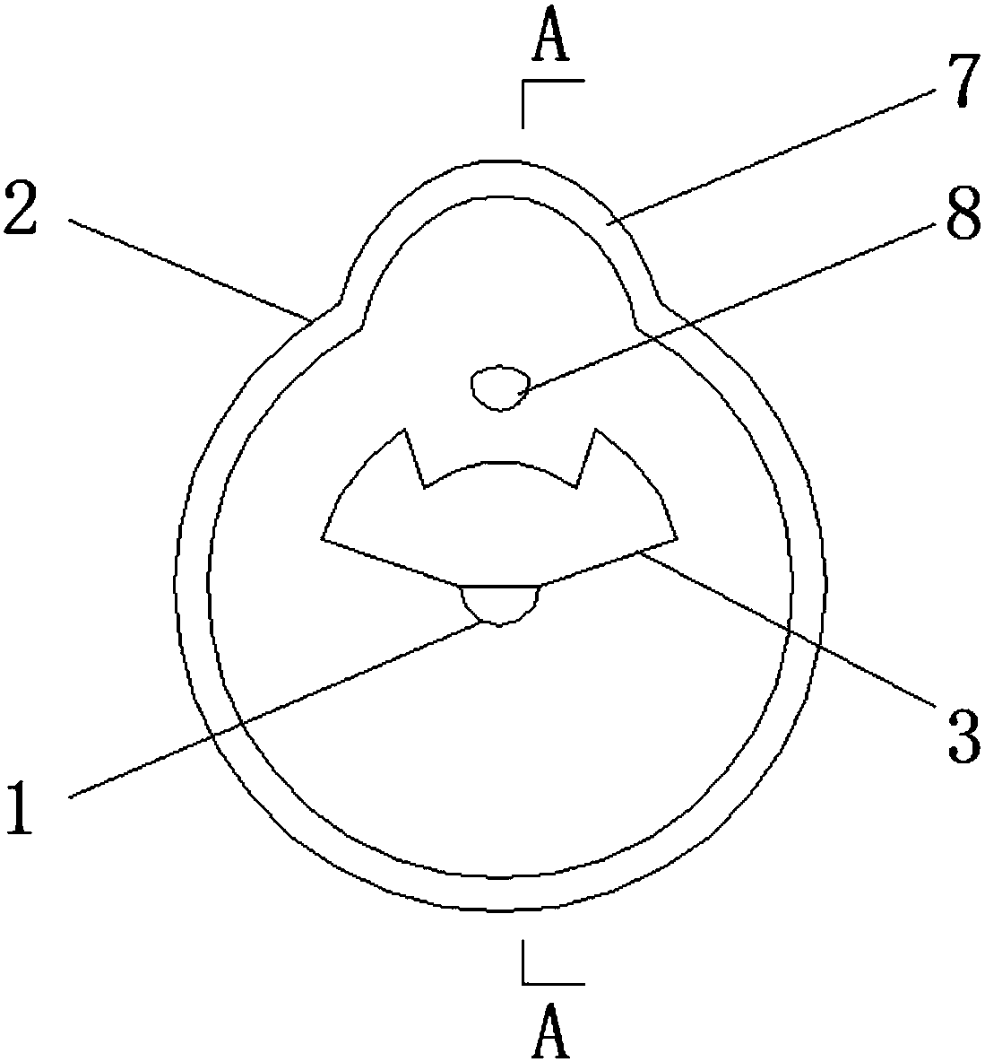
[0043] In the optional scheme of this embodiment, such as figure 1 , figure 2 As shown, a high beam lamp provided in this embodiment includes a light source body 1, a reflective bowl 2, a weak light part 7, a light reduction part 8 and a light shielding part 3;
[0044] The light source body 1 is arranged on the inner wall of the reflective bowl 2;
[0045] The weak light part 7 is arranged at the end of the reflective bowl 2;
[0046] The dimming part 8 is arranged on the inner wall of the reflective bowl 2;
[0047] The light-shielding part 3 is arranged between the port of the light source body 1 and the reflective bowl 2 or on the light emitting path outside the reflective bowl 2, and the side of the light-shielding part 3 facing the light source body is a matte surface.
[0048] Existing high beams for vehicles, the light directly emitted from the top of the bowl mouth of the reflector bowl of the high beams will produce glare, which will cause glare to the oncoming o...
Embodiment 2
[0074] In the optional scheme of this embodiment, different from Embodiment 1, such as image 3 , Figure 4 As shown, one end of the weak light part 7 is connected to the end of the reflective bowl 2, and the other end of the weak light part 7 exceeds the plane where the port of the reflective bowl 2 is located.
[0075] In this embodiment, the weak light part 7 can be a parabolic reflective surface, so that the bundled light can be reflected in parallel; It can only reflect light downwards without causing glare.
Embodiment 3
[0077] In the optional scheme of this embodiment, different from Embodiment 1, such as Figure 5 , Figure 6 As shown, the weak light portion 7 protrudes toward the inner circumference of the reflective bowl 2 .
[0078] In this embodiment, it should be noted that the light reduction unit 8 may not be provided.
PUM
 Abstract
Description
Claims
Application Information
 - R&D
- Intellectual Property
- Life Sciences
- Materials
- Tech Scout
- Unparalleled Data Quality
- Higher Quality Content
- 60% Fewer Hallucinations
Browse by: Latest US Patents, China's latest patents, Technical Efficacy Thesaurus, Application Domain, Technology Topic, Popular Technical Reports.
© 2025 PatSnap. All rights reserved.Legal|Privacy policy|Modern Slavery Act Transparency Statement|Sitemap|About US| Contact US: help@patsnap.com


