Automatic stacking control method for stacking device

A control method and stacking technology, applied in loading/unloading, transportation and packaging, conveyors, etc., can solve problems such as increasing equipment wear, energy consumption, and reducing equipment operating life

Active Publication Date: 2018-06-15
TIDFORE HEAVY IND
View PDF6 Cites 2 Cited by
  • Summary
  • Abstract
  • Description
  • Claims
  • Application Information

AI Technical Summary

Problems solved by technology

[0002] In the stacking process of the storage yard, the maximum stacking capacity is usually designed, and then the unloading member of the stacking device is fixed at the apex of the maximum stacking capacity for unloading. After the unloading is completed, the scraper machine takes the material; but Often the incoming material in the storage yard is not the designed maximum stacking capacity, or the material needs to be taken out if the maximum storage capacity is not reached, or some materials need to be taken away before the maximum storage capacity is reached, such as Figure 5-7 At this time, the stockpile cannot completely fill the stockyard with materials, and the stockpile type is not close to the discharge port. When the reclaimer starts to work, the working surface at the bottom cannot touch the stockpile, and part of the scraped materials cannot be scraped. After being picked up by the system belt conveyor and transported away, it can only be transferred to the discharge port in the material yard, and there is a problem of doing virtual work. This process is called flat material in the industry. This process is time-consuming, energy-consuming, waste of manpower, and increases Equipment wear and tear, reducing the operating life of equipment and increasing the workload of equipment maintenance

Method used


Image

  • Automatic stacking control method for stacking device
  • Automatic stacking control method for stacking device
  • Automatic stacking control method for stacking device

Examples


Embodiment Construction

[0040] The present invention will be described in detail below in conjunction with the accompanying drawings. The description in this part is only exemplary and explanatory, and should not have any limiting effect on the protection scope of the present invention. In addition, those skilled in the art can make corresponding combinations of features in the embodiments in this document and in different embodiments according to the descriptions in this document.

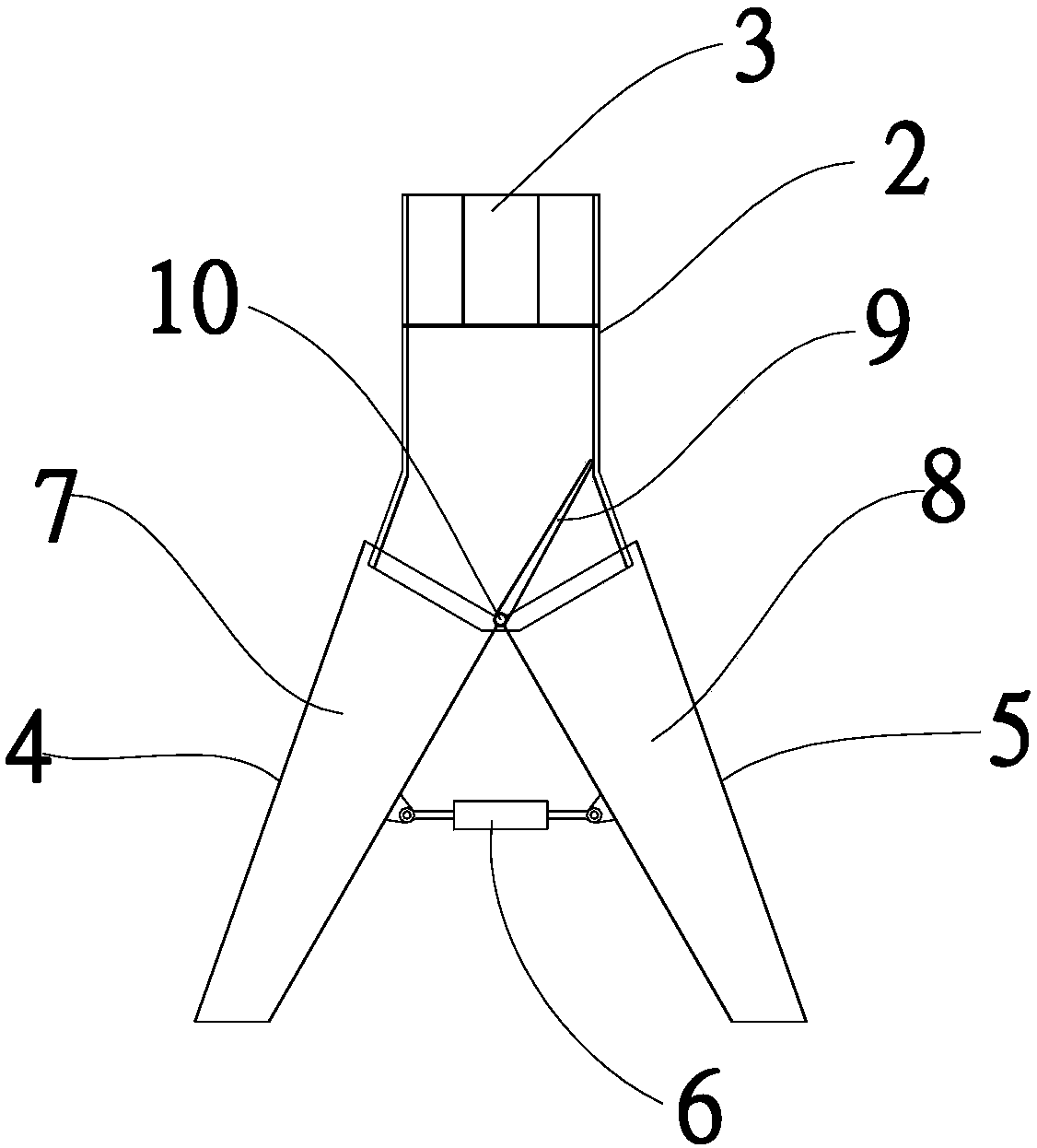
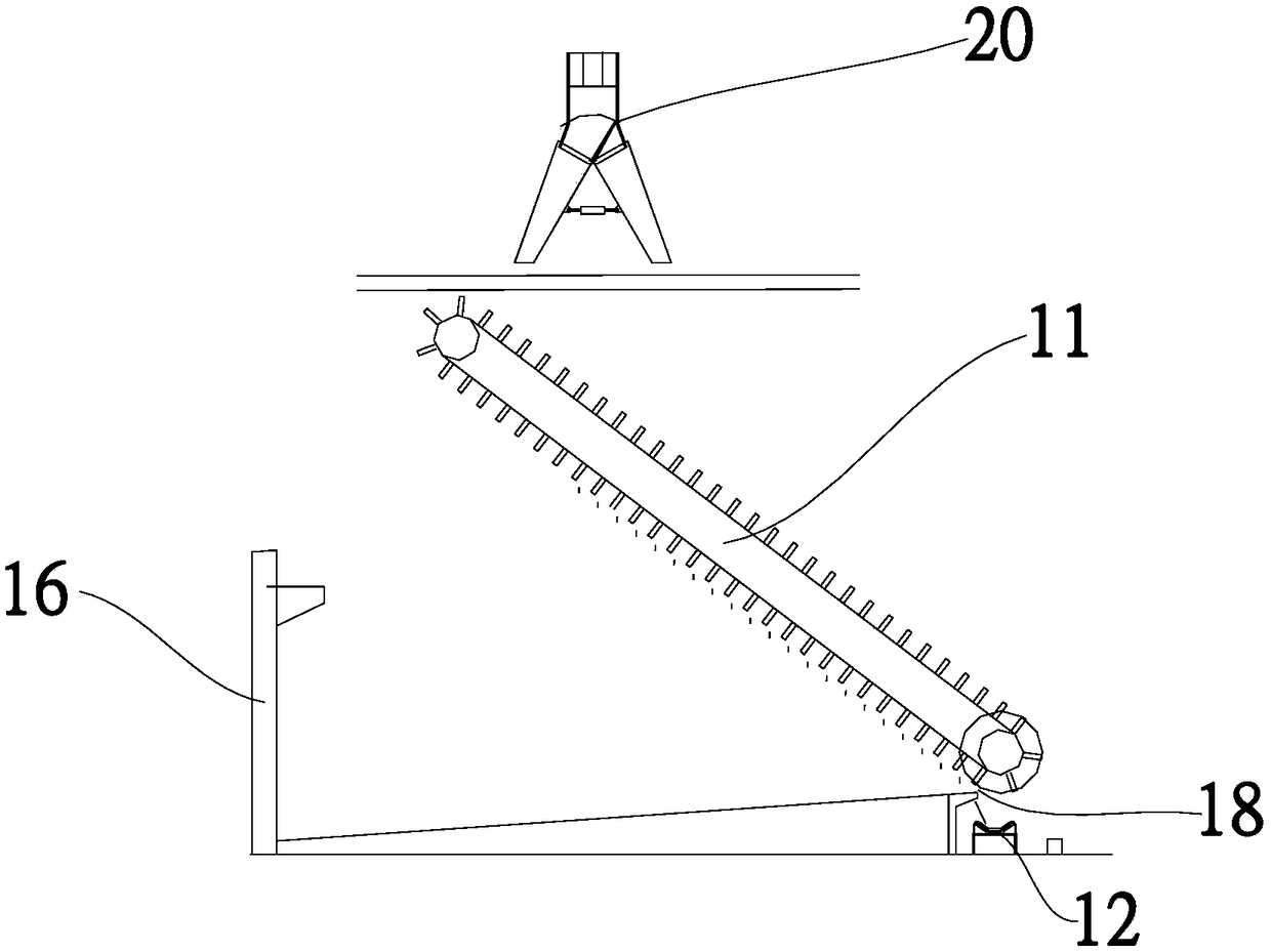
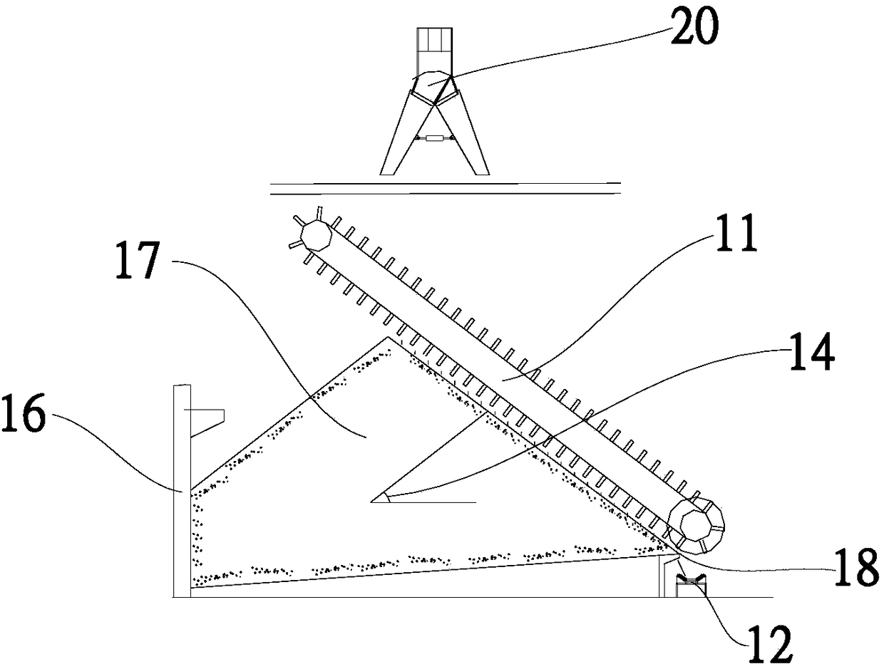
[0041] Embodiments of the present invention are as follows, with reference to 2, image 3 , Figure 4 and Figure 8 , a control method for automatic stacking of a stockpiling device, the stockpiling device includes a material unloading mechanism 20, a detection module and a control module, and the detection module includes at least a geographical feature for detecting the geographical features of the stockyard Appearance detection device 1 and the position detection device for detecting the position of the feeding open...


PUM


Abstract

The invention relates to an automatic stacking control method for a stacking device. The stacking device comprises a discharging mechanism, a detection module and a control module. The automatic stacking control method comprises the following specific steps that (1), the first geometrical cross-section, in the width direction, of a material pile under the maximum reserve amount of materials in a storage yard is calculated and determined; (2), an optimal discharging point is determined; (3), the discharging point of the discharging mechanism of the stacking device is positioned to the optimum discharging point; and (4), the staking operation is performed by the stacking device. According to the automatic stacking control method, it is ensured that a pile type is close to a discharging opening on the premise of meeting material stacking, it is ensured that the working face of the bottom of a scraper taking mechanism can be in contact with the material pile during work, the problem of thevirtual work is prevented, meanwhile the utilization ratio of the stock yard is fully ensured, and the stacking capacity of the stacking and taking equipment is played, so that the defects that an existing bulk material yard is low in degree of automation, low in working efficiency and low in site utilization rate, and the labor intensity of operators is high are overcome.

Description

technical field [0001] The invention belongs to the technical field of loading and unloading, and in particular relates to a control method for automatic stacking of a stacking device. Background technique [0002] In the stacking process of the storage yard, the maximum stacking capacity is usually designed, and then the unloading member of the stacking device is fixed at the apex of the maximum stacking capacity for unloading. After the unloading is completed, the scraper machine takes the material; but Often the incoming material in the storage yard is not the designed maximum stacking capacity, or the material needs to be taken out if the maximum storage capacity is not reached, or some materials need to be taken away before the maximum storage capacity is reached, such as Figure 5-7 At this time, the stockpile cannot completely fill the stockyard with materials, and the stockpile type is not close to the discharge port. When the reclaimer starts to work, the working sur...

Claims


Application Information

Patent Timeline
IPC IPC(8): B65G65/00B65G65/06
CPCB65G65/005B65G65/06B65G2201/04
Inventor 张佳佳孟庆耀甘德慧冯苹
Owner TIDFORE HEAVY IND
Why Eureka
Try Eureka