Slipper brake of maglev train

A technology for maglev trains and brakes, which is applied in the direction of brakes interacting between brake elements and rails, railway braking systems, and railway car body components. The effect of reducing mechanical wear and reducing vertical vibration

Inactive Publication Date: 2018-06-15
SOUTHWEST JIAOTONG UNIV
6 Cites 3 Cited by

AI-Extracted Technical Summary

Problems solved by technology

[0004] The purpose of the present invention is to provide a sliding brake of a maglev train, which can effec...

Abstract

The invention provides a slipper brake of a maglev train, and relates to the technical field of maglev train brake. The slipper brake of the maglev train includes a line sleeper and a suspension frame, wherein cantilever type magnetic steel rails are both arranged on the two sides of the line sleeper. The cross section of the suspension frame is of a semi closed structure, the top portion and twosides of the semi closed structure are closed, an opening is formed in the middle section of the bottom portion of the semi closed structure, and cantilevers are arranged on the two side of the semi closed structure. Electromagnets are arranged on the upper surface, located on the lower portion of the far ends of the magnetic steel rails, of the cantilevers on the two side of the bottom portion. Rubber pads are arranged on the inner surface, located on the upper portion of the near ends of the magnetic steel rails, of the two sides of the suspension frame. Brake sliders are fixed with steel plates on the lower surfaces of the rubber pads through bolts. The steel plates are both arranged on the upper surface and the lower surface of the rubber pads, and the steel plates are fixed with the rubber pads through a plate vulcanization process. The rubber pads are fixed with the inner surface of the top portion of the suspension frame by the steel plates on the upper surface. The material hardness of the brake sliders is less than the material hardness of the magnetic steel rails. The slipper brake of the maglev train is mainly used for the braking of the maglev train.

Application Domain

Railway tracksTrack-braking member co-operation

Technology Topic

Image

  • Slipper brake of maglev train
  • Slipper brake of maglev train

Examples

  • Experimental program(1)

Example Embodiment

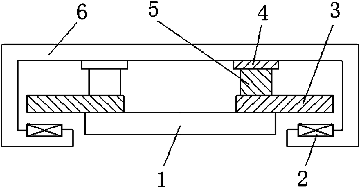
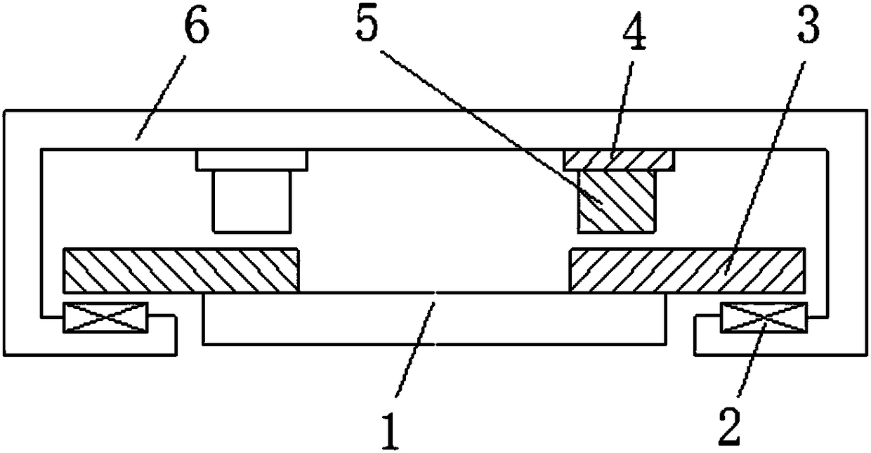
[0012] In order to further understand the content, features, and effects of the present invention, the following embodiments are listed and described in detail with the accompanying drawings as follows:
[0013] Examples such as figure 1 As shown, a sliding brake of a maglev train includes a line sleeper 1 and a suspension frame 6. Both sides of the line sleeper 1 are provided with cantilevered magnetically conductive steel rails 3. The cross section of the suspension frame 6 is the top and the two sides are closed on three sides, and the bottom A semi-closed structure with openings in the middle section and cantilever arms on both sides. Electromagnets 2 are provided on the upper surface of the cantilever on both sides of the bottom and below the far end of the magnetically conductive steel rail 3. The inner surfaces on both sides of the top of the suspension frame 6 are located on the magnetically conductive steel rail. 3 A rubber pad 4 is provided above the proximal end, and the brake slider 5 is fixed to the steel plate on the lower surface of the rubber pad 4 by bolts.
[0014] The upper and lower surfaces of the rubber pad 4 are provided with steel plates, and the steel plates are fixed to the rubber pads through a plate vulcanization process.
[0015] The rubber pad 4 is fixed to the inner surface of the top of the suspension frame 6 through the steel plate on the upper surface.
[0016] The material hardness of the brake slider 5 is less than the material hardness of the magnetically conductive steel rail 3.
[0017] When the train is running, the maglev train is in a suspended state, and there is a suspension gap between the bottom of the brake slider 5 and the magnetic steel rail 3. When the train is braking, the bottom of the braking slider 5 is in contact with the upper surface of the magnetically conductive steel rail 3, and the train is braked by friction.
[0018] Such as figure 2 As shown, if you want to brake smoothly in the levitation state so that passengers do not feel the impact, the levitation force provided by the electromagnet 2 cannot be cancelled immediately but gradually. Therefore, the positive pressure on the brake slider 5 gradually rises to the weight of the vehicle. The frictional force generated with the magnetically conductive steel rail 3 gradually increases. Under emergency braking conditions, the suspension force is immediately cancelled and the maglev train is directly braked on the rails. The dynamic calculation effect of the present invention is relatively satisfactory. For example, the carriage weight is 36 tons, the speed is 200km/h, and the passenger is comfortably overloaded such as 0.13G to implement braking. The braking distance is more than 1,200 meters and the duration is 44.5 seconds, which is equivalent to that of a wheel-rail train.

PUM

no PUM

Description & Claims & Application Information

We can also present the details of the Description, Claims and Application information to help users get a comprehensive understanding of the technical details of the patent, such as background art, summary of invention, brief description of drawings, description of embodiments, and other original content. On the other hand, users can also determine the specific scope of protection of the technology through the list of claims; as well as understand the changes in the life cycle of the technology with the presentation of the patent timeline. Login to view more.

Similar technology patents

Traditional Chinese medicine decoction device

ActiveCN105287216AReduces the risk of inconsistent decoction quality or drug mix-upsSave installation spacePharmaceutical product form changeDomestic articlesMedicinal herbsEngineering
Owner:永春县产品质量检验所福建省香产品质量检验中心国家燃香类产品质量监督检验中心福建

Emergency rescue vehicle

PendingCN107653920ARealize collaborative workSave installation spaceMechanical machines/dredgersEndless track vehiclesEngineeringEmergency rescue
Owner:JIANGSU XCMG CONSTR MASCH RES INST LTD

Classification and recommendation of technical efficacy words

  • Reduce mechanical wear
  • Save installation space

Air-conditioner internal unit and air conditioner

PendingCN107525154ASave installation spaceCompact installation spaceCondensate preventionLighting and heating apparatusAirflowSpace requirements
Owner:GREE ELECTRIC APPLIANCES INC OF ZHUHAI
Why Eureka
Try Eureka