Aviation engine bearing and oil receiving ring connection structure

An aero-engine and connection structure technology, applied in the field of aviation accessories, can solve problems such as poor lubrication of bearings, and achieve the effects of easy processing, simplified structure, and good lubrication

Inactive Publication Date: 2018-06-15
AVIC HARBIN BEARING
View PDF6 Cites 3 Cited by
  • Summary
  • Abstract
  • Description
  • Claims
  • Application Information

AI Technical Summary

Problems solved by technology

[0003] The present invention solves the existing problem of poor lubrication of bearings in high-temperature environments of aero-engines, and further provides a connection structure for aero-engine bearings and oil collectors

Method used


Image

  • Aviation engine bearing and oil receiving ring connection structure
  • Aviation engine bearing and oil receiving ring connection structure
  • Aviation engine bearing and oil receiving ring connection structure

Examples


specific Embodiment approach 1

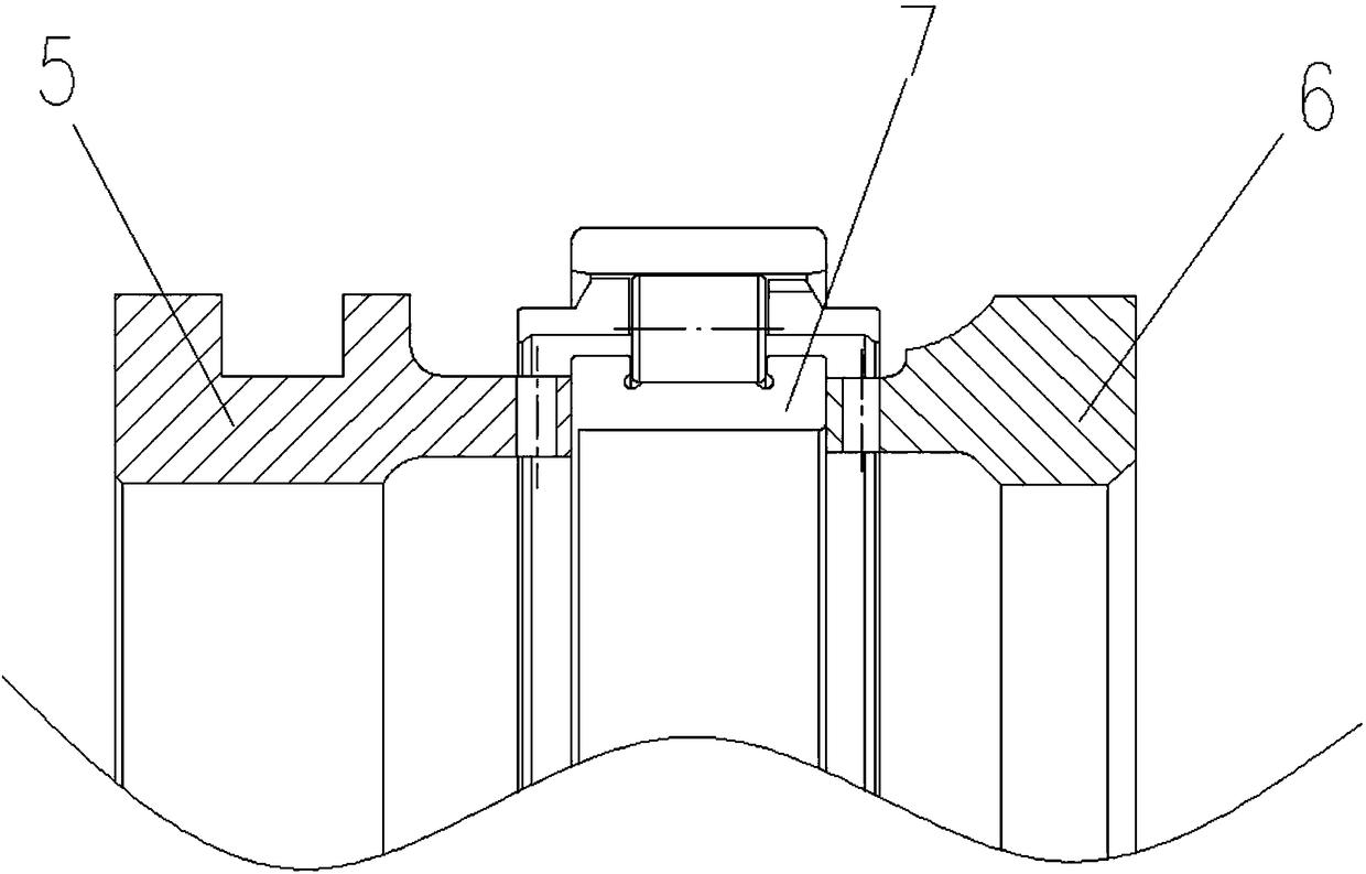
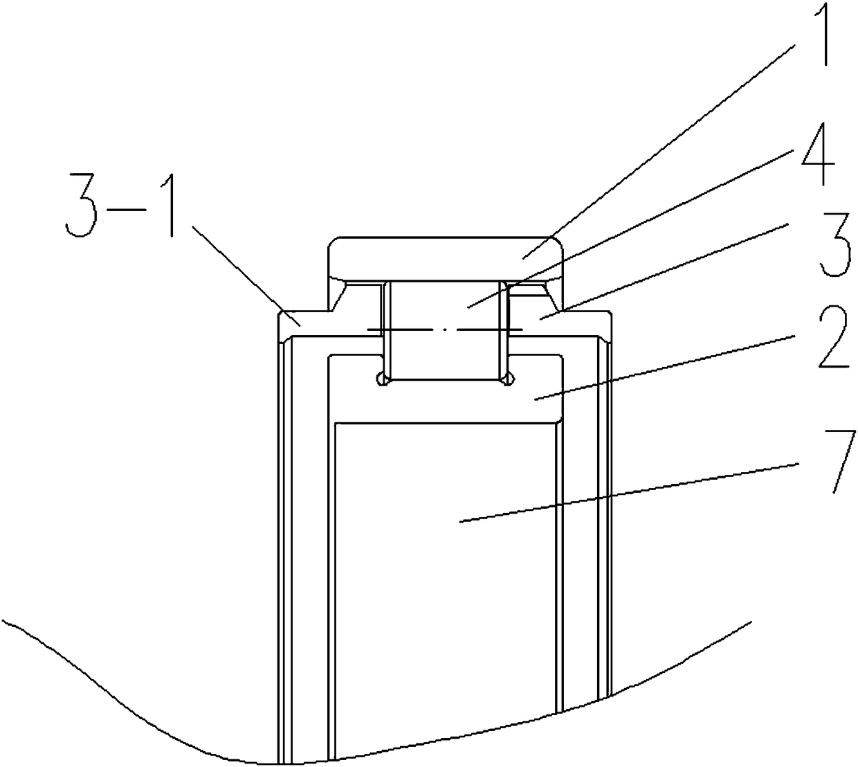
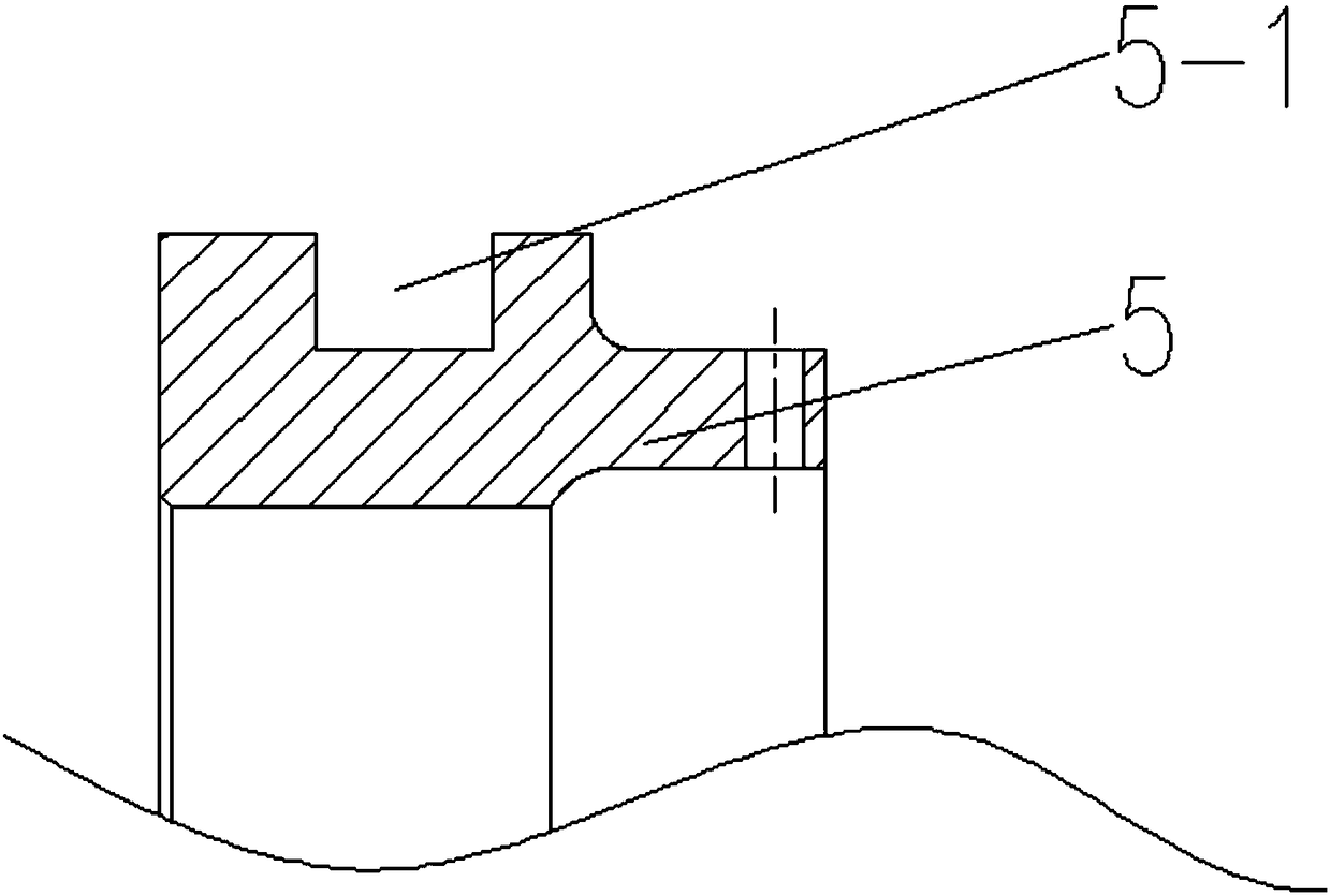
[0010] Specific implementation mode one: combine figure 1 , figure 2 , image 3 and Figure 4 Describe this embodiment, a connection structure for an aero-engine bearing and an oil skimmer described in this embodiment includes a bearing 7, a left oil skimmer 5 and a right oil skimmer 6, and a left oil skimmer 5 and a right oil skimmer 6 are concentrically arranged on both sides of the bearing 7, the bearing 7 includes an outer ring 1, an inner ring 2, a bearing cage 3 and a plurality of rollers 4, and two oil deflecting rings 3 are concentrically arranged on both sides of the bearing cage 3 -1, the outline of the left oil collecting ring 5 is in the shape of a ring, the outer surface of the left oil collecting ring 5 is provided with an annular groove 5-1, and the side of the left oil collecting ring 5 close to the bearing 7 is evenly arranged with a plurality of channels The contour of the right oil collecting ring 6 is in the shape of a ring, and the side of the right oi...

specific Embodiment approach 2

[0011] Specific implementation mode two: combination figure 1 and figure 2 This embodiment is described. This embodiment further limits the bearing described in Embodiment 1. In this embodiment, the outer sides of the two oil deflector rings 3 - 1 are provided with 45-degree chamfers. This design prevents lubricating oil from being thrown out of the bearing due to centrifugal force.


PUM


Abstract

The invention provides an aviation engine bearing and oil receiving ring connection structure and particularly relates to the aviation engine bearing and oil receiving ring connection structure. The aviation engine bearing and oil receiving ring connection structure comprises a bearing, a left oil receiving ring and a right oil receiving ring, the left oil receiving ring and the right oil receiving ring are concentrically arranged on two sides of the bearing correspondingly, the bearing comprises an outer ring, an inner ring, a bearing holder and a plurality of rollers, two sides of the bearing holder are concentrically provided with two oil blocking rings, the outline of the left oil receiving ring is in a circular ring shape, the periphery of the outer surface of the left oil receiving ring is provided with an annular groove, the side, close to the bearing, of the left oil receiving ring is provided with a plurality of through holes in an evenly distributed manner, the outline of theright oil receiving ring is in a circular ring shape, the side, close to the bearing, of the right oil receiving ring is provided with a plurality of through holes in an evenly distributed manner, and the left oil receiving ring and the right oil receiving ring communicate with the rollers through the through holes and an annular gap formed by the bearing holder and the inner ring. The aviation engine bearing and oil receiving ring connection structure is used for aviation engine bearing lubrication.

Description

technical field [0001] The invention belongs to the technical field of aviation accessories, and in particular relates to a connection structure of an aeroengine bearing and an oil collector ring. Background technique [0002] The cage of the bearing of the existing aero-engine under high temperature is a conventional cage, and the lubrication method is side spray. When the bearing rotates at a high speed, it cannot better meet the bearing lubrication requirements, and part of the lubricating oil will be ejected. In the process of high temperature, due to the problem of poor lubrication, the bearings frequently experience early fatigue failures. In severe cases, the engine will have a shaft lock phenomenon, leading to serious consequences of engine shutdown. Contents of the invention [0003] In order to solve the existing problem of poor lubrication of bearings in high-temperature environments of aero-engines, the invention further provides a connecting structure for aero...

Claims


Application Information

Patent Timeline
Patent Type & Authority Applications(China)
IPC IPC(8): F16C33/46F16C33/66
CPCF16C33/46F16C33/664
Inventor 邱贺群寇思源冯小川胡北刘森段继明孙慧琳安浩俊刘新宇范红伟
Owner AVIC HARBIN BEARING
Why Eureka
Try Eureka