Quantitative cutting device for construction steel bars
A cutting device and a technology for building steel bars, applied in the field of quantitative cutting devices for building steel bars, can solve the problems of easy ejection of steel bars and injury to workers, and achieve the effect of preventing steel bars from falling too high
- Summary
- Abstract
- Description
- Claims
- Application Information
AI Technical Summary
Problems solved by technology
Method used
Image

Examples
Embodiment 1
[0037] A quantitative cutting device for building steel bars, such as Figure 1-Figure 5 As shown, it includes a support backboard 1, a support stand 2, a placement board 3, a limit bottom block 4, a cutting chainsaw 5, a lifting mechanism 6 and a drive mechanism 7, and the middle of the front side of the support backboard 1 is symmetrically fixed left and right The support stand 2, the top of the left and right sides of the support stand 2 is connected with a placing plate 3 by means of bolts, the placing plate 3 is fixedly connected with the supporting back plate 1, and the left side of the top of the placing plate 3 is fixedly connected to the limiting bottom block 4, The front and rear sides of the limiting bottom block 4 are rotatably provided with balls, the supporting back plate 1 is provided with a lifting mechanism 6, the lifting mechanism 6 is provided with a driving mechanism 7, and the driving mechanism 7 is provided with a cutting electric saw 5, and the cutting el...
Embodiment 2
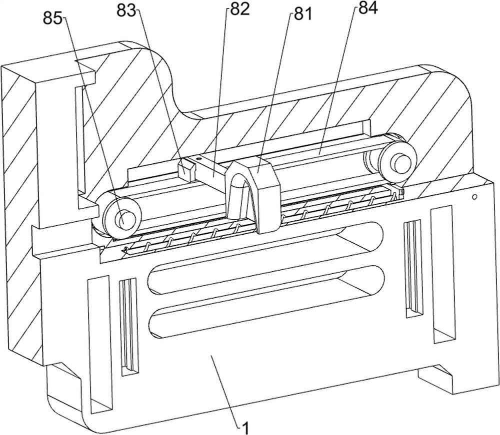
[0042] On the basis of Example 1, as Figure 6-Figure 8 As shown, it also includes a limiting mechanism 8, which includes a limiting vertical block 81, a connecting cross bar 82, a mounting bottom block 83, a positioning belt assembly 84, a transmission horizontal shaft 85, a limiting bottom plate 86, a second reset guide The column 87 and the second return spring 88, the upper right side of the support back plate 1 is slidably provided with a connecting cross bar 82, and the front side of the connecting cross bar 82 is fixedly connected to a limiting block 81, and the limiting block 81 can avoid the reinforcement of the steel bar. The rear part of the connecting cross bar 82 is fixedly connected with the installation bottom block 83, the upper side of the right part of the support back plate 1 is provided with a horizontal transmission shaft 85 in a left-right symmetrical rotation, and a positioning belt assembly is connected between the middle parts of the horizontal transmis...
Embodiment 3
[0049] On the basis of Example 1 and Example 2, as Figure 12 and Figure 15 As shown, it also includes a discharging mechanism 11. The discharging mechanism 11 includes a fixed connecting rod 111, a stripping block 112, a fourth reset guide post 113, and a fourth reset spring 114, which are connected to the lower side of the rear of the vertical plate 74. There is a fourth reset guide post 113. The fourth reset guide post 113 is slidably provided with a fixed connecting rod 111. The front end of the fixed connecting rod 111 is fixed with a stripping block 112, and the stripping block 112 can push the steel bar downward. The fourth reset guide post 113 is wound with a fourth reset spring 114 , one end of the fourth reset spring 114 is connected to the connecting vertical plate 74 , and the other end of the fourth reset spring 114 is connected to the fixed link 111 .
[0050] When the telescopic rod of the electric push rod 61 is stretched, the connecting vertical plate 74 mov...
PUM
 Abstract
Description
Claims
Application Information
 - R&D
- Intellectual Property
- Life Sciences
- Materials
- Tech Scout
- Unparalleled Data Quality
- Higher Quality Content
- 60% Fewer Hallucinations
Browse by: Latest US Patents, China's latest patents, Technical Efficacy Thesaurus, Application Domain, Technology Topic, Popular Technical Reports.
© 2025 PatSnap. All rights reserved.Legal|Privacy policy|Modern Slavery Act Transparency Statement|Sitemap|About US| Contact US: help@patsnap.com