Battery machining robot

A robot and battery technology, applied in primary batteries, battery assembling machines, equipment for manufacturing primary batteries, etc., can solve the problems of high labor intensity, difficult to grasp, cumbersome and complicated processes, etc., to reduce labor intensity and improve work efficiency. , the effect of simple operation

Active Publication Date: 2018-08-31
JIAXING HENGWEI BATTERY
View PDF4 Cites 12 Cited by
  • Summary
  • Abstract
  • Description
  • Claims
  • Application Information

AI Technical Summary

Problems solved by technology

[0003] In order to solve the above problems, the present invention provides a battery processing robot, which can solve the need for personnel to grab different types of batteries during the existing battery production process. The process is cumbersome and complicated. It is easy for people to jump when grabbing, and it is not easy to grab manually. When grabbing for a long time, the personnel may be dazzled and miss the grasping phenomenon. When grabbing the cylindrical battery, the personnel usually grab the middle of the cylindrical battery. In actual operation , the grasped cylindrical battery may fall off due to sweating of the hands, the process takes a long time, the labor intensity is high, and the efficiency is low. It can realize the function of automatically grabbing different types of cylindrical batteries and button batteries, and automate the processing of cylindrical batteries. Carrying out multiple limited grabs, the cylindrical battery will not fall off, and the button battery will not be missed, no manual operation is required, the time is short, and it has the advantages of simple operation, low labor intensity and High work efficiency and other advantages

Method used


Image

  • Battery machining robot
  • Battery machining robot
  • Battery machining robot

Examples


Embodiment Construction

[0032] In order to make the technical means, creative features, goals and effects achieved by the present invention easy to understand, the present invention will be further described below in conjunction with specific illustrations. It should be noted that, in the case of no conflict, the embodiments in the present application and the features in the embodiments can be combined with each other.

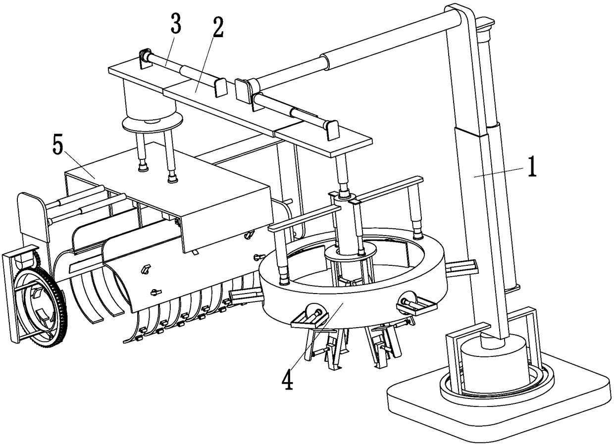
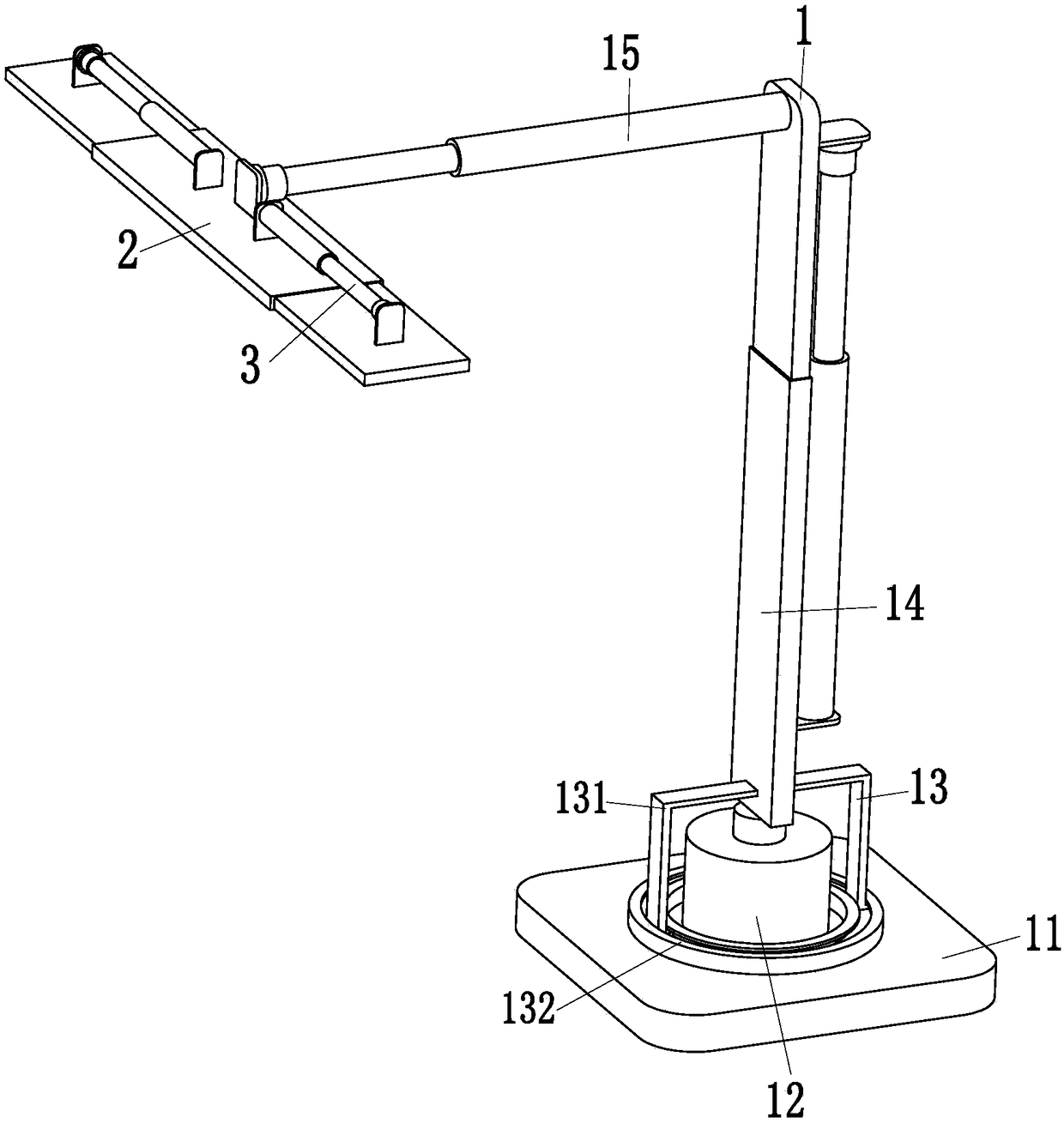
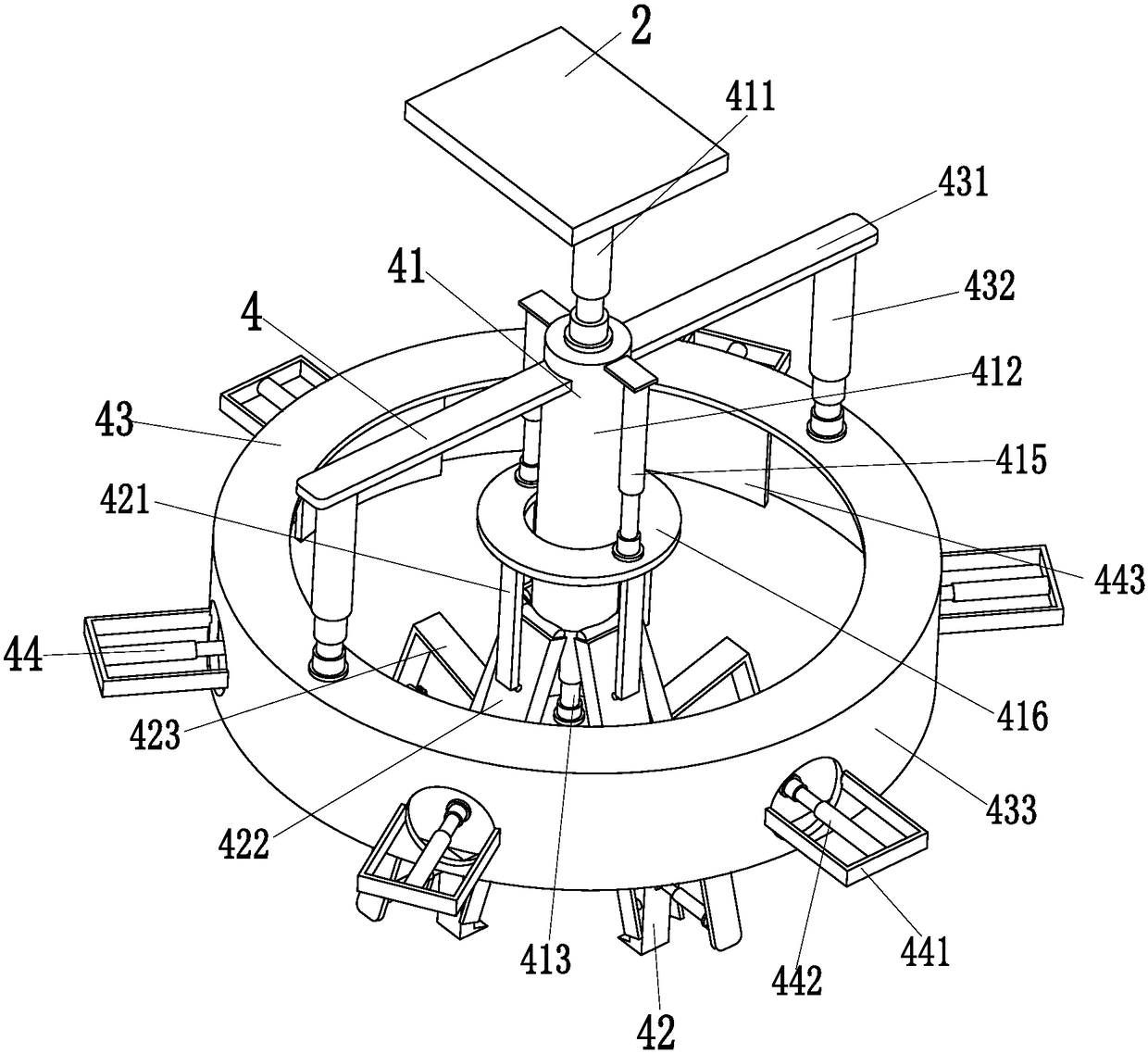
[0033] Such as Figure 1 to Figure 6 As shown, in order to achieve the above object, the present invention adopts the following technical solutions: a battery processing robot, including an adjustment device 1, a bidirectional telescopic plate 2, two symmetrical cylinders 3, a button battery clamping device 4 and a cylindrical battery clamping device 5 , the adjustment device 1 drives the present invention to adjust the orientation, the button battery clamping device 4 clamps the button battery, and the cylindrical battery clamping device 5 clamps cylindrical batteries of different t...


PUM


Abstract

The invention relates to a battery machining robot. The battery machining robot comprises an adjusting device, a two-way telescopic plate, two symmetric air cylinders, a button battery clamping deviceand a cylindrical battery clamping device; the front end of the adjusting device is installed at the upper end of the two-way telescopic plate, the two symmetric air cylinders are installed in the middle of the two-way telescopic plate, and the top ends of the symmetrical air cylinders are installed at the outer ends of the two-way telescopic plate through flanges; and the button battery clampingdevice is installed on the right side of the lower end of the two-way telescopic plate, and the cylindrical battery clamping device is installed on the left side of the lower end of the two-way telescopic plate. According to the battery machining robot, the problems that in the present process of producing batteries, people need to grab the different types of batteries, when the button battery isgrabbed, due to the fact that the button battery is relatively small, jumping and flying of the button battery are prone to occurrence during grabbing by people, and people possibly have blurred vision and then miss grabbing the button battery during long-term grabbing, and in addition, when a cylindrical battery is grabbed, people usually grab the middle part of the cylindrical battery, and thenthe grabbed cylindrical battery possibly falls off due to sweating of hands can be solved.

Description

technical field [0001] The invention relates to the field of battery production, in particular to a battery processing robot. Background technique [0002] A battery refers to a cup, tank or other container or a part of a composite container that contains an electrolyte solution and a metal electrode to generate current. It is a device that can convert chemical energy into electrical energy. It has a positive pole and a negative pole. The performance parameters of the battery mainly include electromotive force. , capacity, specific energy and resistance, using the battery as an energy source, you can get a stable voltage, stable current, stable power supply for a long time, and a current that is little affected by the outside world, and the battery structure is simple, easy to carry, and the charging and discharging operation is simple and easy. , not affected by the external climate and temperature, stable and reliable performance, play a great role in all aspects of modern...

Claims


Application Information

Patent Timeline
Patent Type & Authority Applications(China)
IPC IPC(8): B25J11/00B25J15/00H01M6/00H01M10/04
CPCB25J11/00B25J15/0052H01M6/005H01M10/0404Y02P70/50
Inventor 潘岳燕
Owner JIAXING HENGWEI BATTERY
Why Eureka
Try Eureka