Tea leaf withering process plant

A kind of processing equipment and tea technology, which is applied in the direction of tea processing before extraction, etc., to meet the requirements of large-scale production, improve quality, and save space

Inactive Publication Date: 2008-08-20
林清矫
View PDF0 Cites 31 Cited by
  • Summary
  • Abstract
  • Description
  • Claims
  • Application Information

AI Technical Summary

Problems solved by technology

[0003] The present invention aims to solve the problems existing in the above-mentioned prior art, and provides a simple and practical tea withering treatment equipment to solve various disadvantages caused by the existing withering production method of repeated shaking and airing. , greatly improving work efficiency and raw tea quality

Method used


Image

  • Tea leaf withering process plant
  • Tea leaf withering process plant
  • Tea leaf withering process plant

Examples


Embodiment 1

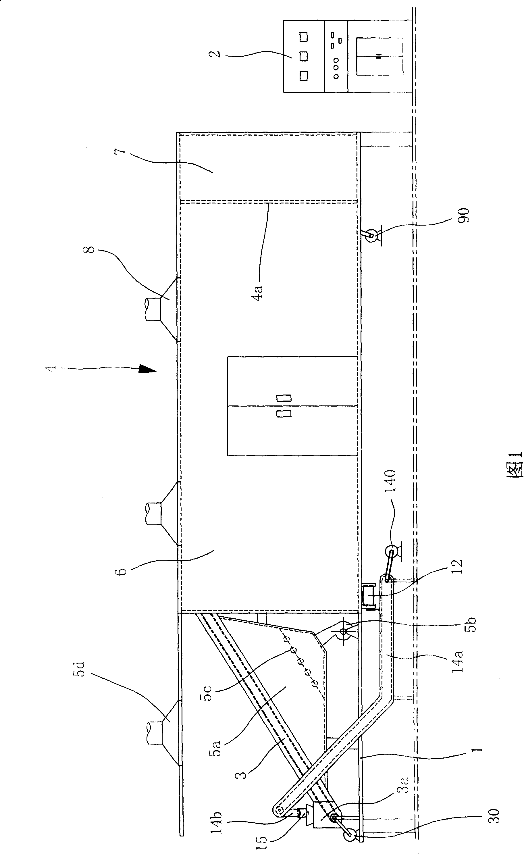
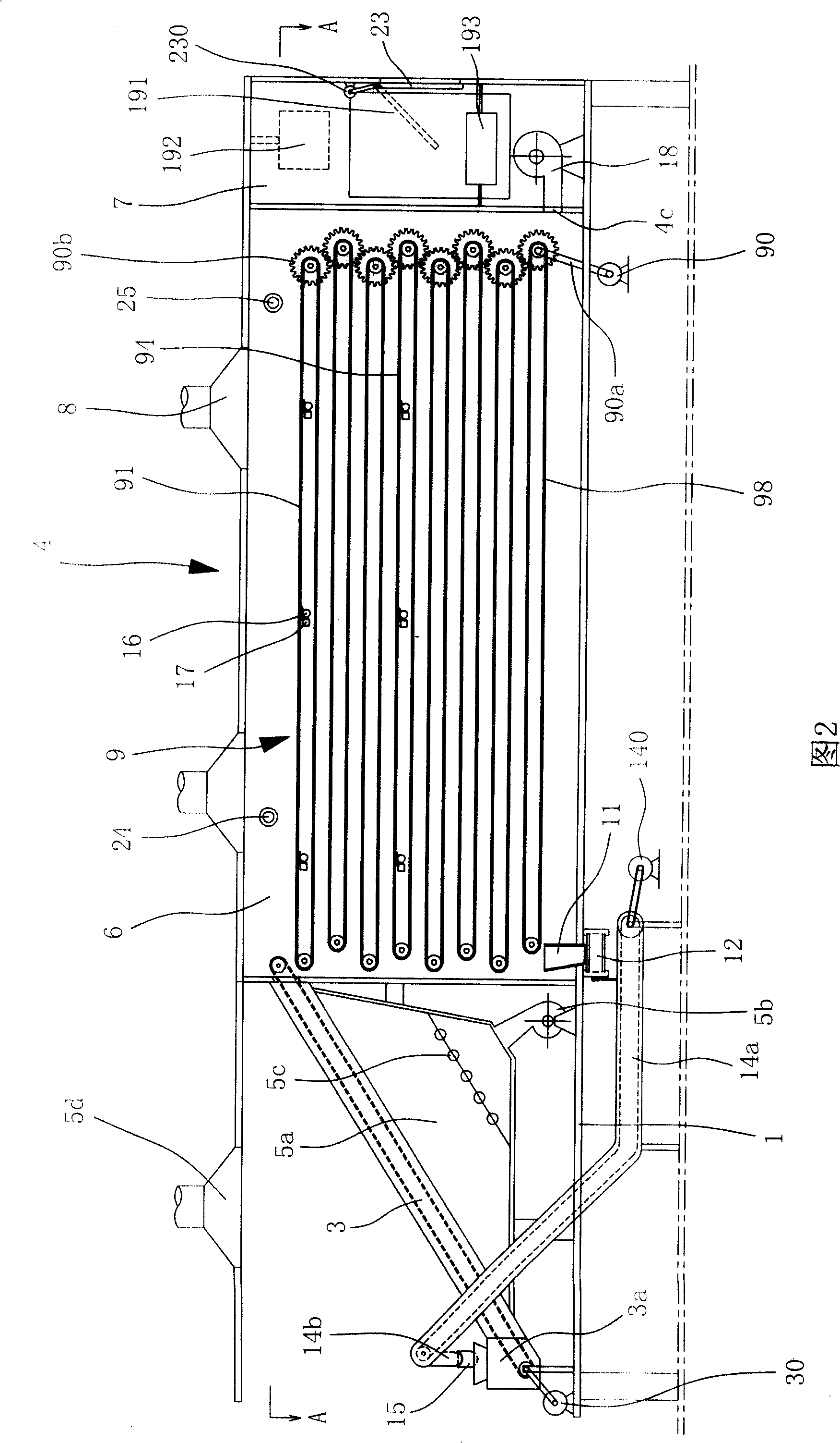
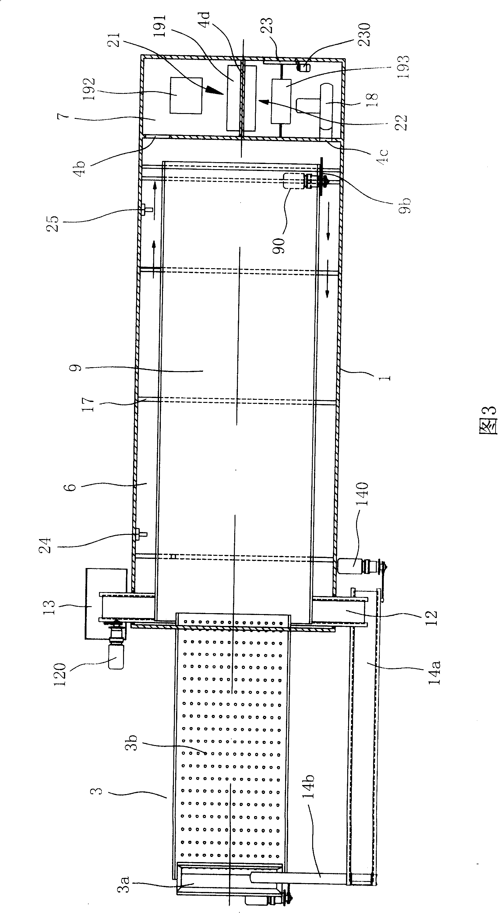
[0017] Embodiment 1: With reference to Fig. 1. The tea withering treatment equipment mainly includes a frame 1, an electric control box 2, a feeding conveyor belt 3 installed on the frame 1, a box body 4, a cold and hot air supply device, a discharge conveyor belt, and a loop return device. Below in conjunction with Fig. 1 to Fig. 3, the structure of this embodiment is described in detail:

[0018] Material lifting conveyor belt 3 is installed on the front upper part of frame 1 by support, and casing 4 is fixedly installed on the frame 1 of material lifting conveyor belt 3 rear portions. The driving motor 30 fixed on the frame 1 is connected with the transmission of the material lifting conveyor belt 3, and the driving motor 30 drives the material lifting conveyor belt 3 to rotate through the belt. The loading end of the material-lifting conveyor belt 3 is provided with a hopper 3a, and the discharge end passes through the side plate of the box body 4 and extends into the top...

Embodiment 2

[0027] Embodiment 2: as shown in Figure 5. The present embodiment is different from Embodiment 1 in that: the discharge conveyor belt 12 is directly arranged on the inner bottom of the tea green treatment chamber 6 below the discharge port end of the lowermost conveyor belt 98, and on the both sides of the tea green treatment chamber 6 Correspondingly, an opening 26 for the discharge conveyor belt 12 to pass through is provided, and the two ends of the discharge conveyor belt 12 protrude out of the dark green processing chamber 6 through the corresponding openings 26 . The tealeaves sent out by the lowermost conveyor belt 98 directly falls on the discharge conveyor belt 12, and the material passing port is no longer provided. The rest of the structure is the same as that of Embodiment 1, and will not be repeated here.


PUM


Abstract

The invention provides a tea withering machine, comprising a frame, an electric cabinet and a case on the rear part of the frame. A feeding and conveying belt for delivering tealeaves into the case is arranged on the frame in front of the case; small vent holes are densely arranged on the conveying belt, and a heating and cooling air supplying device is positioned under the conveying belt; the case is divided into a tealeaves treating chamber and an air treatment chamber by a separating plate with respective air inlets and outlets at both sides; the air treatment chamber is provided with a temperature and humidity treatment device for recirculation air, and a blower; the blower is connected with the air outlets of the separating plate; the tealeaves treating chamber is provided with an air exhausting device and a multi-layer tealeaves distributing and conveying belt; the tealeaves distributing and conveying belt is used to support the tealeaves on the feeding and conveying belt, and deliver downward the tealeaves layer-by-layer; a conveying belt for the discharge tealeaves is arranged at the lower part of a discharge port of the lowest tealeaves distributing and conveying belt; a circulating and back-feeding device for delivering the tealeaves to a hopper is arranged between one end of the conveying belt for the discharge tealeaves and the hopper; a receiving chute is positioned below the other end of the conveying belt for the discharge tealeaves; a temperature and humidity sensor connected with an input end of a control system is arranged in the tealeaves treatment chamber. The tea withering machine has the advantages of saved space and excellent withering effects.

Description

technical field [0001] The invention relates to the field of tea-making machinery, in particular to a device for withering tea greens after picking. Background technique [0002] Depending on the type of tea, the production process is different, but withering treatment is the first process that all tea production processes must go through, and it is also the basic process for forming the quality of tea. Withering refers to the process of dehydrating the picked fresh tea leaves after a period of time, causing the hard and brittle fresh tea leaves to wilt and wither, making the leaves soft, highly plastic and easy to shape. Withering has both the physical dehydration effect and the chemical change process of the contained substances; one is to evaporate part of the water, reduce the tension of the tea cells, make the leaf stems from brittle to soft, increase the toughness of the buds and leaves, and facilitate kneading. The second is a series of chemical changes in the substa...

Claims


Application Information

Patent Timeline
Patent Type & Authority Applications(China)
IPC IPC(8): A23F3/06
Inventor 林清矫
Owner 林清矫
Why Eureka
Try Eureka