A press dehydrator

A dehydrator, a press-type technology, applied in mechanical equipment, washing devices, textiles and papermaking, etc., can solve problems such as insufficient use of time and energy, inability to meet the speed of dehydration of clothes, and inability to dehydrate clothes.

Inactive Publication Date: 2017-10-13
BEIJING TECHNOLOGY AND BUSINESS UNIVERSITY
View PDF6 Cites 0 Cited by
  • Summary
  • Abstract
  • Description
  • Claims
  • Application Information

AI Technical Summary

Problems solved by technology

[0002] The dehydrator is an indispensable household appliance in people's life today. However, most of the current dehydrators are electric dehydrators. In places without electricity, the washed clothes cannot be dehydrated. Long-term non-drying brings a lot of inconvenience to people's daily life, and the dehydration speed of the electric dehydrator is a certain value, which cannot meet the needs of the dehydration speed of clothes of various materials; Go to some fitness places for fitness in this way of exercise, this kind of exercise cannot make full use of time and energy

Method used


Image

  • A press dehydrator
  • A press dehydrator
  • A press dehydrator

Examples


Embodiment Construction

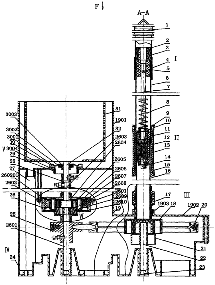
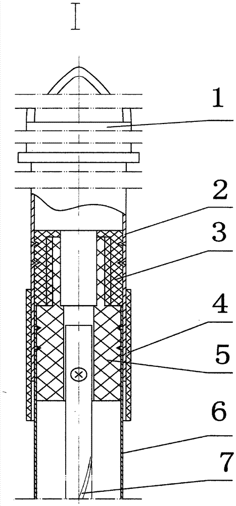
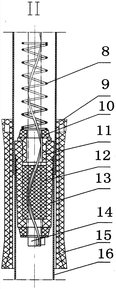
[0043] Figure 1 to Figure 3 Shows a preferred embodiment of the present invention, as shown in the figure, the press-type dehydrator of the present invention is mainly composed of a base, a pair of splined input shafts and support shafts, an outer barrel, a planetary gear speed increaser combination, It is composed of a pulley transmission mechanism, a combination of sealing water bowls, a combination of dehydration cylinders, and a combination of up and down moving and rotating devices.

[0044] The base 24 is positioned at the lowermost end of the device, and the upper end of its circumference outer wall is an outer low inner high step wall 2401 ( Figure 1-04 ), see figure 1 , figure 2 , image 3 , Figure 1-04 , Figure 1-05 , Figure 1-06 , in the illustrated embodiment, its left and right parts each have a protruding groove, the groove is a cylindrical hole, and a ball 23 is placed at the bottom of the hole. A pair of spline input shafts 2601 and support shafts 22...


PUM


Abstract

A press-type water-removing device comprises a pedestal, a pair of spline input shaft and a support shaft, the spline input shaft and the support shaft are respectively arranged at the left and the right in the same row, and are respectively mounted in raised grooves in the left portion and the right portion of the pedestal. An outer drum is assembled on the pedestal, a planetary gear speed increaser assembly is fixedly mounted to a column at the bottom of the outer drum, an output shaft of the planetary gear speed increaser is the spline input shaft, the middle portion of the spline input shaft is connected with a belt pulley driving transmission mechanism used for driving the spline input shaft to rotate, and an output shaft of the planetary gear speed increaser is connected to a water-removing drum via a couple in the axial direction. A sealing bowl assembly is fixed to a central hole in the bottom of the outer drum. A support rod at the upper portion of the supporting shaft is sleeved by a device capable of moving upwards and downwards and rotating, an upper connecting member of the device is connected to a middle tube and a screw, the screw is sleeved by a screw column, a lower connecting member is connected to the screw column and a lower tube, and the lower tube is connected to the belt pulley driving transmission mechanism. The screw can move when pressed, then the screw column rotate, the middle tube moves upwards and downwards in the lower tube to drive the belt pulley driving transmission mechanism to rotate. By adopting the press-type water-removing device, a user can remove water in clothes by hands, the resources can be saved, and the application of the device is wide.

Description

technical field [0001] The invention belongs to the technical field of home appliances, in particular to a dehydrator. Background technique [0002] The dehydrator is an indispensable household appliance in people's life today. However, most of the current dehydrators are electric dehydrators. In places without electricity, the washed clothes cannot be dehydrated. Long-term non-drying brings a lot of inconvenience to people's daily life, and the dehydration speed of the electric dehydrator is a certain value, which cannot meet the needs of the dehydration speed of clothes of various materials; Going to some fitness places for fitness with this kind of exercise method, this kind of exercise method cannot make full use of time and energy. [0003] The dehydrator that combines fitness and clothes dehydration is not only energy-saving but also able to dry clothes, which is green and environmentally friendly. The press-type dehydrator can achieve the purpose of dehydrating clot...

Claims


Application Information

Patent Timeline
Patent Type & Authority Patents(China)
IPC IPC(8): D06F47/00F16H37/02
CPCD06F47/00F16H37/02
Inventor 项辉宇冷崇杰
Owner BEIJING TECHNOLOGY AND BUSINESS UNIVERSITY
Why Eureka
Try Eureka