Mounting arrangement for crossing arm

a technology of mounting arrangement and crossbar, which is applied in the direction of vehicular safety arrangement, bumper, pedestrian/occupant safety arrangement, etc., can solve the problems of not being able to significantly dampen vibration transmitted, the oltrogge bracket cannot pivotally support the crossbar beam or the like, and the hard guide and bumper bracket cannot fit flush against the front surface of a bus bumper that has nothing. , to achieve the effect of dampening vibration transmitted

Inactive Publication Date: 2001-07-03
SPECIALTY MFG CO INC
View PDF12 Cites 12 Cited by
  • Summary
  • Abstract
  • Description
  • Claims
  • Application Information

AI Technical Summary

Benefits of technology

In accordance with this invention a crossing arm assembly mounting bracket is provided that includes a back surface having a non-planar profile contoured to complement the profile of the front surface of the bumper the bracket is to be mounted on. The mounting bracket is part of a crossing arm assembly that pivotally attaches to a bumper at the front end of a vehicle such as a bus. The crossing arm assembly also includes an elongated beam having an inner end pivotally supported on the mounting bracket. The crossing arm beam swings out to block pedestrian traffic from crossing immediately in front of the vehicle when the vehicle is stopped. When bolted together, the complementary contours of the mounting bracket and bumper provide a strong mechanical interlock that resists the downward movement that the cantilevered beam applies to the mounting bracket.
According to another aspect of the invention, the beam includes a longitudinal protrusion that extends laterally inward toward the bumper from a bumper-side of the beam. The guide includes a downward-facing generally horizontal surface extending outward from the front surface. This downward15 facing horizontal surface is spaced opposite the upward-facing horizontal surface to form a guide socket. The guide socket is dimensioned to receive the beam protrusion when the beam is in the stowed position. This prevents the beam from bouncing on the guide when the vehicle is under way.

Problems solved by technology

A disadvantage of this crossing arm assembly is that the bumper must be modified to include an elongated recess.
However, the Oltrogge bracket is not configured to pivotally support a crossing arm beam or to significantly dampen vibrations transmitted between the vehicle bumper and the bracket.
A disadvantage of the Harder bumper-mounted guide design is that, when the crossing arm is in the stowed position, the ramped guide surface tends to urge the arm to slide outward and away from the bumper.
In addition, the Harder guide and bumper bracket could not fit flush against the front surface of a bus bumper that has anything other than a flat profile.

Method used


Image

  • Mounting arrangement for crossing arm
  • Mounting arrangement for crossing arm
  • Mounting arrangement for crossing arm

Examples


Embodiment Construction

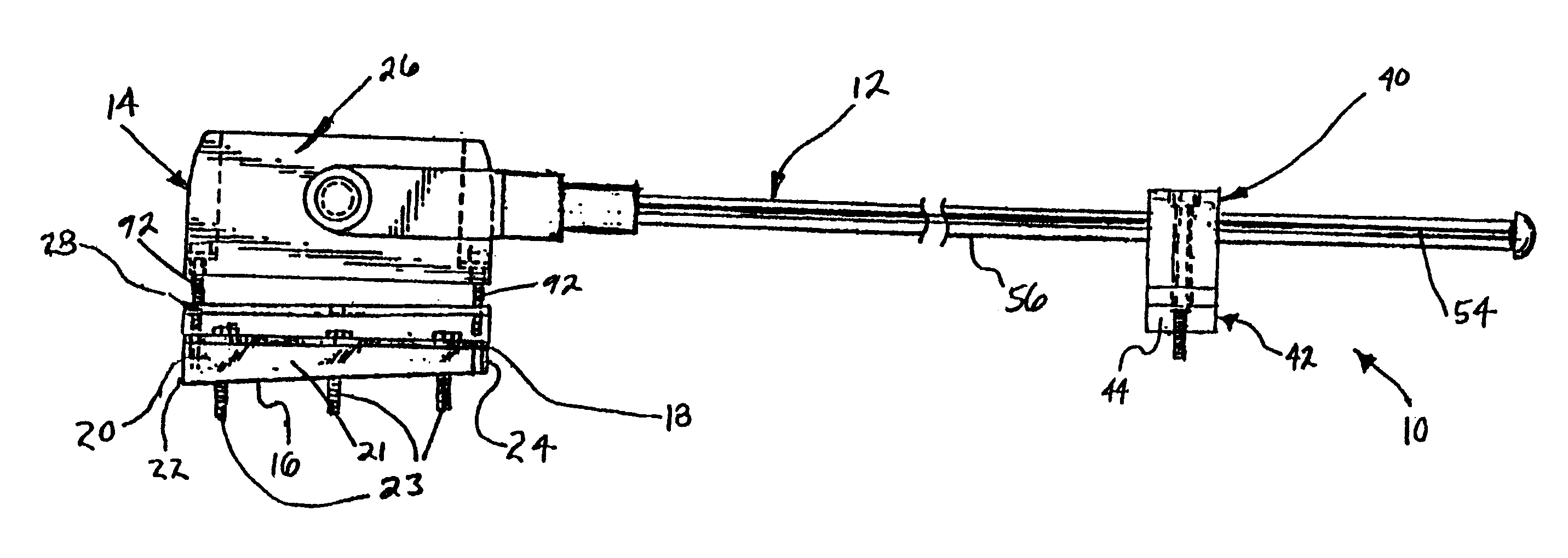
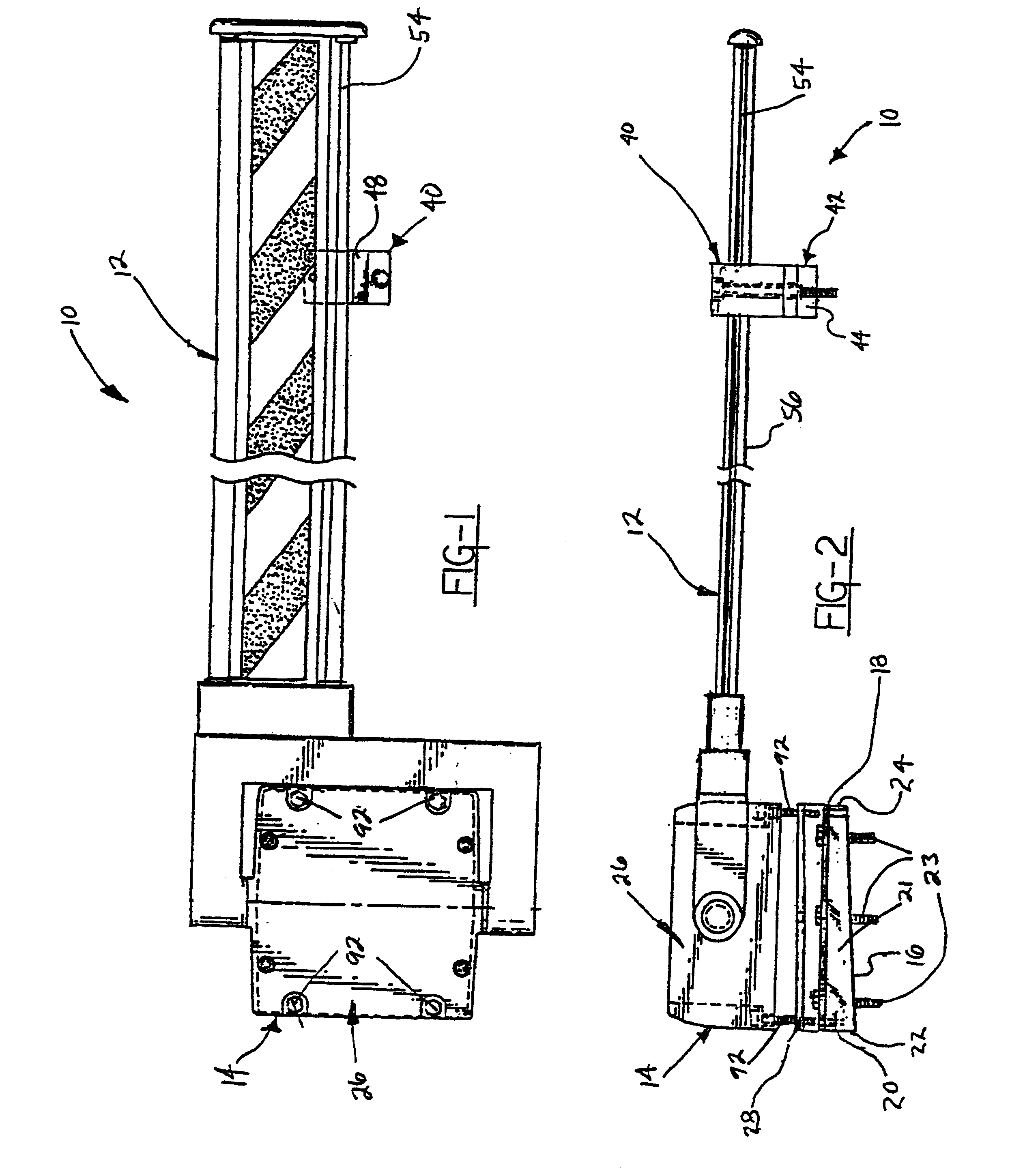
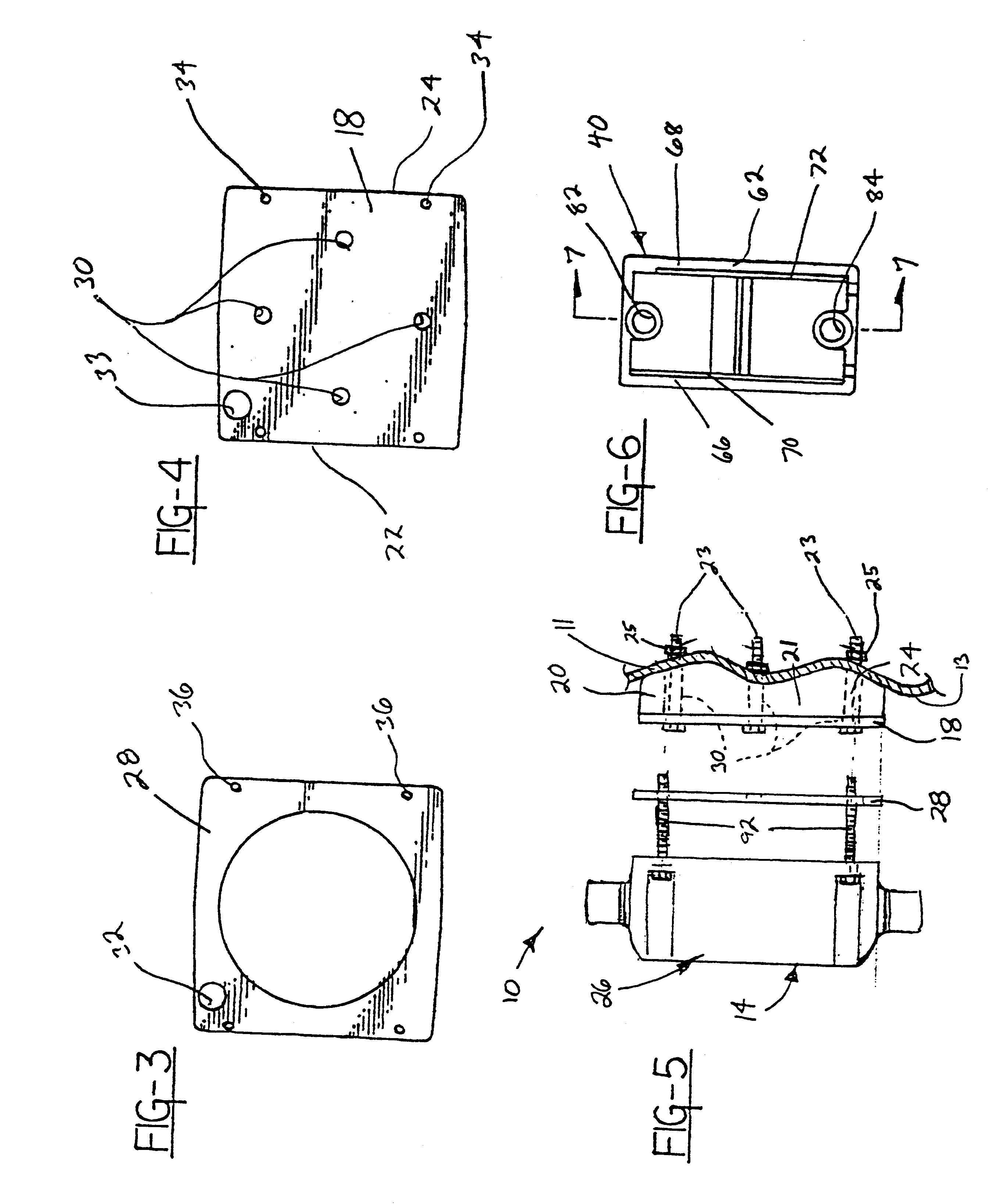
A crossing arm assembly is generally shown at 10 in FIGS. 1, 2 and 5. The assembly 10 attaches to a bumper 11 at the front end of a vehicle. The assembly includes an elongated horizontally oriented arm or beam generally indicated at 12 in FIGS. 1, 2 and 11. The beam 12 swings out from a stowed position along the front bumper 11 to block pedestrian traffic from crossing immediately in front of the vehicle when the vehicle is stopped. The crossing arm assembly 10 also includes a mounting bracket generally indicated at 14 in FIGS. 1, 2 and 5. The mounting bracket 14 is configured to fixedly mount to the front bumper 11. The crossing arm beam 12 has an inner end pivotally supported on the mounting bracket 14. The mounting bracket 14 includes a back surface 16 having a non-planar profile contoured to complement the profile of a front surface 13 of a vehicle bumper.

The mounting bracket 14 includes a generally square face plate 18 that is part of a bracket adapter. The bracket adapter 20 h...


PUM


Abstract

A crossing arm assembly that pivotally attaches to a bumper at the front end of a vehicle such as a bus to block pedestrian traffic from crossing immediately in front of the vehicle when the vehicle is stopped. The assembly includes a mounting bracket configured to fixedly mount to the front bumper of a vehicle, the front bumper having a front surface having a profile common to the bumpers of other vehicles of the same make and model. The assembly also includes an elongated beam having an inner end pivotally supported on the mounting bracket. The bracket includes a back surface having a non-planar profile contoured to complement the profile of the front surface of the bumper. The assembly is made by providing a mounting bracket having a back surface profile contoured to complement the non-planar front surface profile of the bumper of the make and model of vehicle the assembly is to be mounted to. The beam is pivotally supported on the mounting bracket either before or after the mounting bracket is fastened to the bumper.

Description

This invention relates generally to safety equipment for school busses and more particularly to a mounting arrangement for a crossing arm assembly configured to mount on the front end of a school bus.INVENTION BACKGROUNDSchool bus crossing arms are designed to extend to a perpendicular position relative to a front bus bumper when a school bus stops to pick up or discharge passengers. In this perpendicular position, such a crossing arm will block arriving and departing passengers from crossing immediately in front of a school bus and below the bus driver's field of vision. U.S. Pat. No. 5,357,239, granted to me Oct. 18, 1994, shows such a crossing arm assembly, or "safety gate," pivotally mounted to a housing or mounting bracket. The mounting bracket includes a single flat back plate that fixedly mounts to the front bumper of a vehicle. The back plate includes holes or slots for receiving mounting bolts.U.S. Pat. No. 3,153,398, granted Oct. 20, 1964 to George LaVeme Runkle and Gilber...

Claims


Application Information

Patent Timeline
Patent Type & Authority Patents(United States)
IPC IPC(8): B60R19/02B60R19/48B60R21/00
CPCB60R19/48B60R2021/0067
Inventor LAMPARTER, RONALD C.
Owner SPECIALTY MFG CO INC
Why Eureka
Try Eureka