Horizontal pushing device for wall tilt laser test

A technology of moving devices and inclinations, applied in active optical measuring devices, measuring devices, measuring instruments, etc., can solve problems such as difficult to measure distance, difficult to level ruler, difficult to obtain detection results, etc.

Active Publication Date: 2018-06-15
浙江宏业检测科技有限公司
View PDF6 Cites 3 Cited by
  • Summary
  • Abstract
  • Description
  • Claims
  • Application Information

AI Technical Summary

Problems solved by technology

[0004] However, at present, many buildings have a platform on the second floor. The position of the platform prevents the staff from extending a glass plate 9 directly on the second floor. It is difficult for the staff to measure the distance between the laser point at the bottom of the platform and the wall 1.
In addition, because the width of the platform is relatively large, it is difficult to ensure the level of the ruler during the measurement process by protruding a glass plate 9 directly on one side of the platform, especially when the inclination of the wall 1 is small, it is difficult to obtain better detection. result

Method used


Image

  • Horizontal pushing device for wall tilt laser test
  • Horizontal pushing device for wall tilt laser test
  • Horizontal pushing device for wall tilt laser test

Examples


Embodiment 1

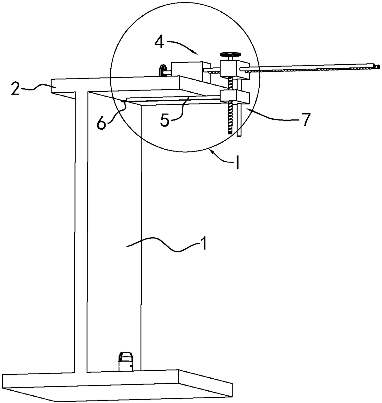
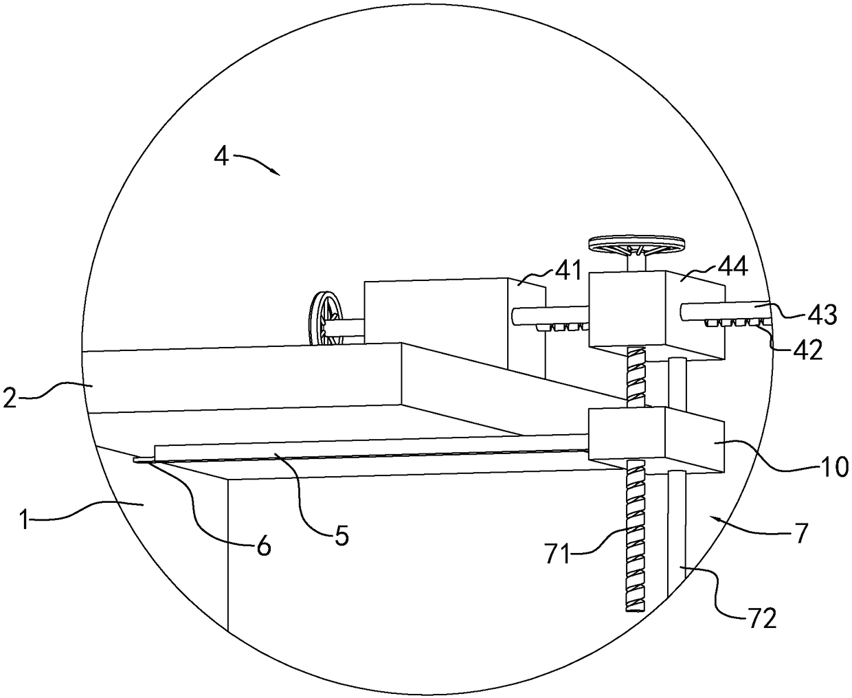
[0033] Embodiment 1, a kind of horizontal moving device for the laser test of the inclination of the wall body 1, see figure 1 and 2 , including the first lead screw structure 4, the first lead screw structure 4 includes a base 41 that can be placed on the platform 2 and auxiliary parts arranged on the base 41, a level can be installed on the top of the base 41, and a level can be installed on the observation level The position of the air bubble to adjust the base 41 to the level.

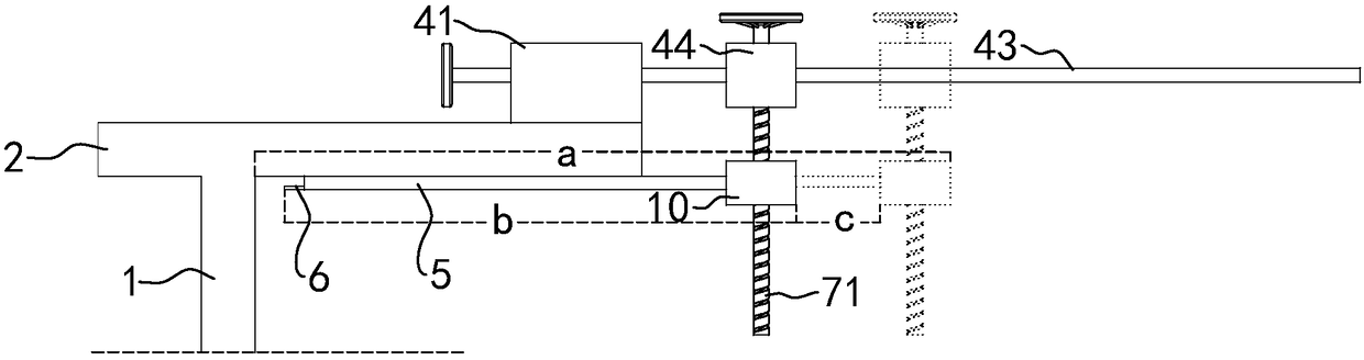
[0034] Auxiliary parts comprise two horizontal screw mandrels 42 and guide rods 43 that are arranged in parallel, wherein the smooth section of the left part of the screw mandrel 42 passes through the base 41 and rotates to fit. In order to improve the smoothness of rotation, the screw mandrel 42 and Bearings are arranged between the bases 41; the left end of the screw rod 42 is fixedly connected with the base 41 coaxially with a hand wheel, and the right part is a threaded part, which is threade...

Embodiment 2

[0038] Embodiment 2, a horizontal moving device for the laser test of the inclination of the wall 1, combined with Figure 4 The difference from Example 1 is that the end of the connecting rod 5 away from the guide block 44 is fixedly connected with an inclined mirror 8, and the laser emitted by the laser marking instrument 3 is irradiated on the mirror 8, which is difficult to observe due to the irradiation on the upper side. Whether the laser has entered the mirror 8, the mirror 8 is set to be inclined, the reflection of the mirror 8 can increase and change the laser path, so that the final landing point of the laser is the ground, as long as the staff downstairs observe the laser appearing on the ground, Then it indicates that the laser light enters into the mirror surface 8 .

[0039]In addition, in order to be able to achieve the completion of the test by only one staff member in this embodiment 2, the mirror surface 8 is installed at an angle of 45° with the horizontal p...


PUM


Abstract

The invention discloses a horizontal pushing device for a wall tilt laser test. The horizontal pushing device comprises a first screw structure on a platform, the first screw structure comprises a base on the platform, a screw passing through the base and rotatingly fitting to the base, a guide rod arranged parallel to the screw and slidably fitting to the base and a guide block connected to the screw through threads and slidably fitting to the guide rod. The guide rod is linked to a connection rod. The connection rod is located below the platform. Laser emitted by a laser marking instrument is irradiated on the bottom surface of the connection rod. The horizontal pushing device has a reasonable structure and can accurately measure the tilt of the wall of the platform.

Description

technical field [0001] The invention relates to a wall inclination testing technology, in particular to a horizontal moving device for wall inclination laser testing. Background technique [0002] When testing the seismic strength of buildings (especially buildings in old building areas), the staff will test the wall inclination of the building, that is, the verticality of the wall. [0003] At present, a simple detection method combined with the Figure 5 As shown, it is that the wall 1 is built on the ground. During the detection process, the staff can place the laser marking instrument 3 on the side of the wall 1 on the ground, and the laser marking instrument 3 can emit vertically upwards. A laser beam, and then the staff places a transparent glass plate 9 on the upper part of the wall 1 (it can be the second floor), the laser passes through the glass plate 9, and the distance from the upper part to the laser point is measured by a ruler as L'; the ruler is used in advan...

Claims


Application Information

Patent Timeline
Patent Type & Authority Applications(China)
IPC IPC(8): G01C15/00
CPCG01C15/002
Inventor 夏进福沈利伟王东江
Owner 浙江宏业检测科技有限公司
Why Eureka
Try Eureka