Device for conducting fatigue performance tests on anchorage device connector and method therefor
A fatigue performance test and connector technology, applied in the field of testing, can solve problems such as poor versatility, high test cost, and unstable test quality, and achieve the effects of high versatility, low test cost, reliable technical foundation and technical services
- Summary
- Abstract
- Description
- Claims
- Application Information
AI Technical Summary
Problems solved by technology
Method used
Image
Examples
Embodiment 1
[0039] The method of the present embodiment comprises the following steps:
[0040] A. Preparing steel strands: Prepare seven steel strands 8 as a group, with a free length greater than 800mm and a specification model of 1×7-15.20-1860, and cut the required steel strands.
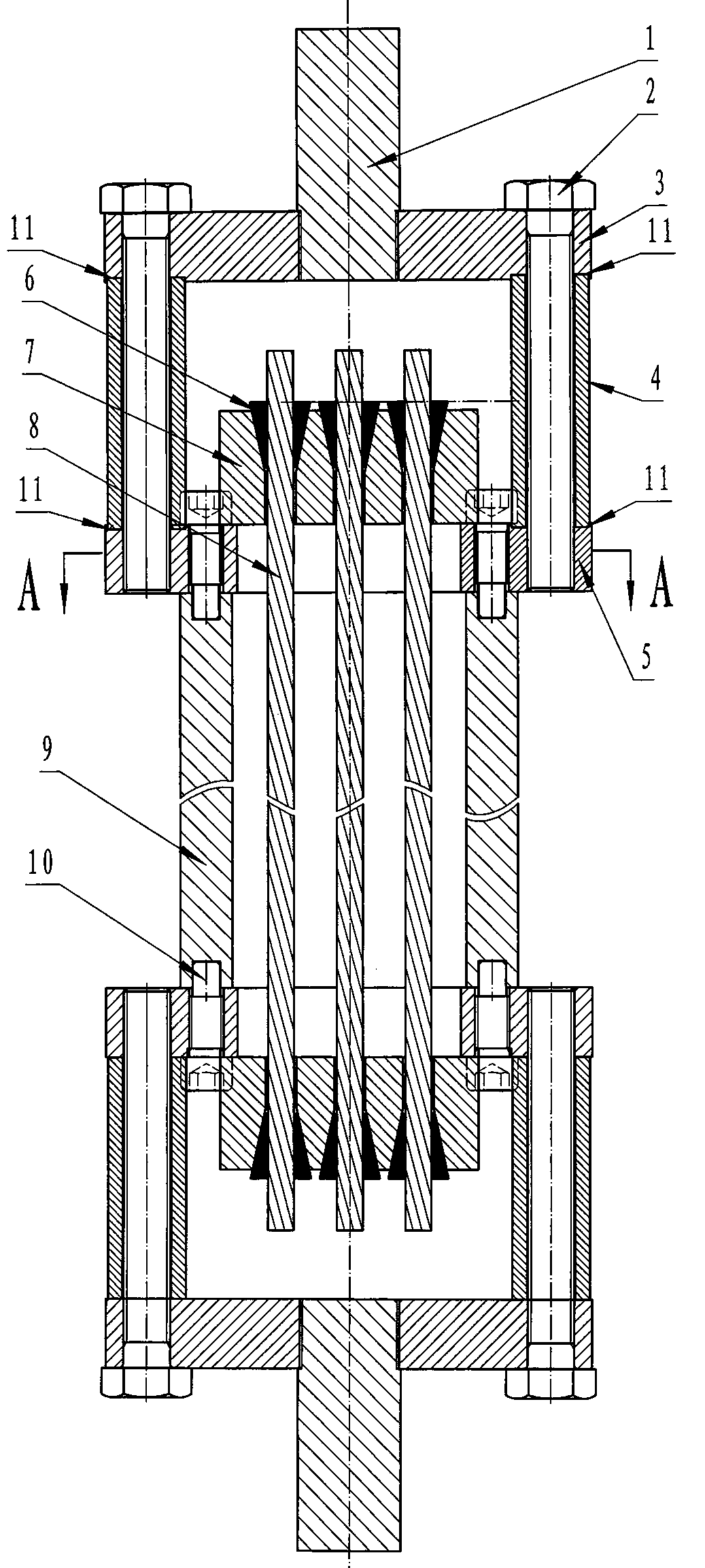
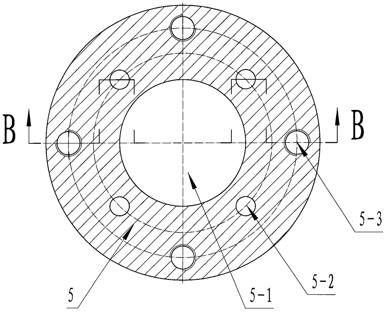
[0041] B. Build the internal structure: first connect one end of four pre-tensioned struts 9 with a length of 1m to a fixed support plate 5 through four positioning bolts 10, and then connect the four pre-tensioned struts 9 through other four positioning bolts 10. The other end of the strut 9 is connected with another fixed support plate 5 to form an I-shaped wheel-shaped internal structure; wherein, the threaded section of the positioning bolt 10 is screwed into the threaded blind hole corresponding to the end of the pre-tensioned strut 9 , the positioning bolt 10 can slide freely in a small gap relative to the fixed support plate 5 in the light hole 5-2.
[0042] C, wear steel strands: wear the prepared ...
Embodiment 2
[0048] The method of the present embodiment comprises the following steps:
[0049] A. Preparing steel strands: prepare six steel strands 8 as a group, free length greater than 800mm, and specifications and models 1×7-15.20-1860, and cut the required steel strands.
[0050] B. Build the internal structure: first connect one end of four pre-tensioned struts 9 with a length of 1m to a fixed support plate 5 through four positioning bolts 10, and then connect the four pre-tensioned struts 9 through other four positioning bolts 10. The other end of the strut 9 is connected with another fixed support plate 5 to form an I-shaped wheel-shaped internal structure; wherein, the threaded section of the positioning bolt 10 is screwed into the threaded blind hole corresponding to the end of the pre-tensioned strut 9 , the positioning bolt 10 can slide freely in a small gap relative to the fixed support plate 5 in the light hole 5-2.
[0051] C, wear steel strands: wear the prepared steel s...
Embodiment 3
[0057] The method of the present embodiment comprises the following steps:
[0058] A. Preparing steel strands: prepare four steel strands 8 as a group, free length greater than 800mm, and specifications and models 1×7-15.20-1860, and cut the required steel strands.
[0059] B. Build the internal structure: first connect one end of four pre-tensioned struts 9 with a length of 1m to a fixed support plate 5 through four positioning bolts 10, and then connect the four pre-tensioned struts 9 through other four positioning bolts 10. The other end of the strut 9 is connected with another fixed support plate 5 to form an I-shaped wheel-shaped internal structure; wherein, the threaded section of the positioning bolt 10 is screwed into the threaded blind hole corresponding to the end of the pre-tensioned strut 9 , the positioning bolt 10 can slide freely in a small gap relative to the fixed support plate 5 in the light hole 5-2.
[0060] C, wear steel strands: wear the prepared steel ...
PUM
 Abstract
Description
Claims
Application Information
 - R&D
- Intellectual Property
- Life Sciences
- Materials
- Tech Scout
- Unparalleled Data Quality
- Higher Quality Content
- 60% Fewer Hallucinations
Browse by: Latest US Patents, China's latest patents, Technical Efficacy Thesaurus, Application Domain, Technology Topic, Popular Technical Reports.
© 2025 PatSnap. All rights reserved.Legal|Privacy policy|Modern Slavery Act Transparency Statement|Sitemap|About US| Contact US: help@patsnap.com


