Tube clamping rack and shaping method thereof

A clamping frame and tube clamping technology, applied in the direction of antenna support/installation device, etc., can solve the problems of poor production accuracy, achieve the effect of improving accuracy, ensuring accuracy, and reducing the number of bending times

Inactive Publication Date: 2018-06-15
江苏亚信电子科技有限公司
View PDF4 Cites 2 Cited by
  • Summary
  • Abstract
  • Description
  • Claims
  • Application Information

AI Technical Summary

Problems solved by technology

[0003] The technical problem to be solved by the present invention is to provide a pinch frame and its forming method, which can solve the problem of poor production accuracy of the product caused by three times of bending in the forming method of the pinch frame

Method used


Image

  • Tube clamping rack and shaping method thereof
  • Tube clamping rack and shaping method thereof
  • Tube clamping rack and shaping method thereof

Examples


Embodiment Construction

[0023] The following examples can enable those skilled in the art to understand the present invention more comprehensively, but the present invention is not limited to the scope of the described examples.

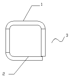
[0024] Such as Figure 1 to Figure 7 A clamping rack shown includes a clamping rack body 4; a bottom area 1, a top area 2 and a side area 3 are provided on the clamping rack body.

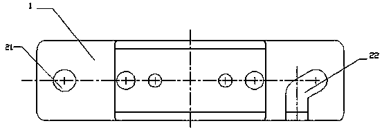
[0025] Two pairs of threaded connection holes 11 are symmetrically arranged on the bottom area 1 .

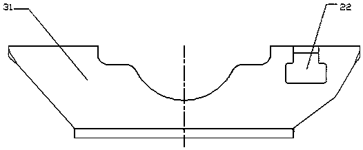
[0026] The side area 3 includes a front side area 31 and a rear side area 32; the front side area 31 and the rear side area 32 are in a mirror image relationship with respect to the center plane of the top area 2; the top area 2 is a rectangular hole structure; The front side area 31 and the rear side area 32 respectively extend to the side area 3 along the sides of the rectangular hole structure in the top area 2 to form a curved hole structure; the rectangular hole structure and the curved hol...


PUM


Abstract

The invention relates to a tube clamping rack. The tube clamping rack is characterized in that the tube clamping rack comprises a tube clamping rack body; the tube clamping rack body is provided witha bottom area, a top surface area and a side area. The shaping method of the tube clamping rack is characterized by including the following steps of: material unloading; punching; first bending; and second bending. The tube clamping rack of the invention is integrally shaped; punching at a plurality of positions of the tube clamping rack body can be completed at one time through the punching stepin a technique process, and at the same time, the precision of the punching can be ensured, and production procedures can be reduced; and in a bending process, bending is performed twice, so the number of the times of bending can be decreased, and therefore, the accuracy of products after the bending is performed can be improved, and the production efficiency of the products can be improved.

Description

technical field [0001] The invention relates to the field of antenna brackets, in particular to a clamping tube bracket and a forming method thereof. Background technique [0002] The pinch frame is generally used as a connecting support device for the connecting pipe on the antenna. In the production process, it is generally produced by cutting, punching and bending thin plates; this production method is high in efficiency and low in cost, and is suitable for popularization. However, in the general forming process, different punching positions and external holes on the clamping frame are often processed according to the connection method and connection position of the connecting tube on the antenna; especially in the bending process, three times of bending are required. The closed bending of the pinch frame can only be completed by bending, and multiple bendings are likely to cause poor manufacturing accuracy of the product. Contents of the invention [0003] The technic...

Claims


Application Information

Patent Timeline
Patent Type & Authority Applications(China)
IPC IPC(8): H01Q1/12B21D35/00
CPCH01Q1/12B21D35/001
Inventor 石明勇沈晓银
Owner 江苏亚信电子科技有限公司
Why Eureka
Try Eureka