Novel weight engaging-type coupler

A gear-type, coupler technology, applied in the field of couplers, can solve the problems of no electricity, the displacement of the reed contact point, the single signal sensing function, etc., and achieve the effect of safe and reliable performance.

Inactive Publication Date: 2018-06-15
林望成
0 Cites 0 Cited by

AI-Extracted Technical Summary

Problems solved by technology

The weight-engagement couplers currently used in the market generally have only five or less external terminals, which are respectively connected to the live wire, neutral wire, ground wire, first signal wire and second signal wire, and can only realize power input work and only have a single signal tra...

Method used

Beneficial effects of the present invention: a kind of weight toothing type coupler provided by the present invention has six connection terminals, and signal connection terminal and signal conductive ring adopt conjoined structure in addition, constitute the electrical appliance weight toothing coupler of reasonable structure , The L-pole reed, N-pole reed, second signal reed, and third signal reed in the connector are all equipped with silver contacts, and the contact mode between the input socket and the connector is the upper and lower plane contact, and the performance is safe and reliable.
Described L pole moving reed 9, N pole moving reed 8, the second signal reed 19 and the third signal reed 24 are all welded with silver contacts, and silver contacts enhance conductivity and circuit connection stability.
Described N pole conductive ring 14 and L pole conductive ring 13 have socket end 26, described N pole moving reed 8 and L pole moving reed 9 are respectively provided with socket hole 27, so The socket hole 27 described above is assembled with the socket end 26, and the socket end 26 is inserted into the socket hole 27, which is convenient for installation and disassembly.
Described connector 3 is provided with a plurality of rings that respectively accommodate the first signal column 10, the second signal ring 15, the third signal ring 16, the N pole conductive ring 14, the L pole conductive ring 13 and the grounding ring 17 Groove for easy installation and protection for related circuit connections.
Described housing is provided with N pole reed 22, L pole reed 23, the 3rd signal reed 24, the second signal reed 19, the first signal reed 20 and grounding reed...

Abstract

The present invention relates to a weight engaging-type coupler. The coupler can solve the problem of the fault of the conventional coupler. The coupler comprises a connector and an appliance input socket. The appliance input socket is provided with a fixing iron plate, a heat bimetallic strip and a fixing seat. The heat bimetallic strip, the fixing iron plate, and the appliance input socket are fixedly assembled successively, the appliance input socket is provided with the fixing seat, the fixing seat is provided with a movable hole and a porcelain rod ejection pole, and the porcelain rod ejection pole is matched with the movable hole movably. The coupler has six wire connection terminals, signal wire connection terminal(s) and signal conducting loop(s) are adopted a connected structure to form the reasonable structure electrical appliance weight engaging-type coupler. A L pole spring piece, a N pole spring piece, a second signal spring piece and a third signal spring piece in a connector are all provided with sliver contact points, the contacting mode of the input socket and the connector is an upper and lower plane contacting, and thus the performance is safe and reliable.

Application Domain

Technology Topic

EngineeringBimetallic strip +1

Image

  • Novel weight engaging-type coupler
  • Novel weight engaging-type coupler
  • Novel weight engaging-type coupler

Examples

  • Experimental program(1)

Example Embodiment

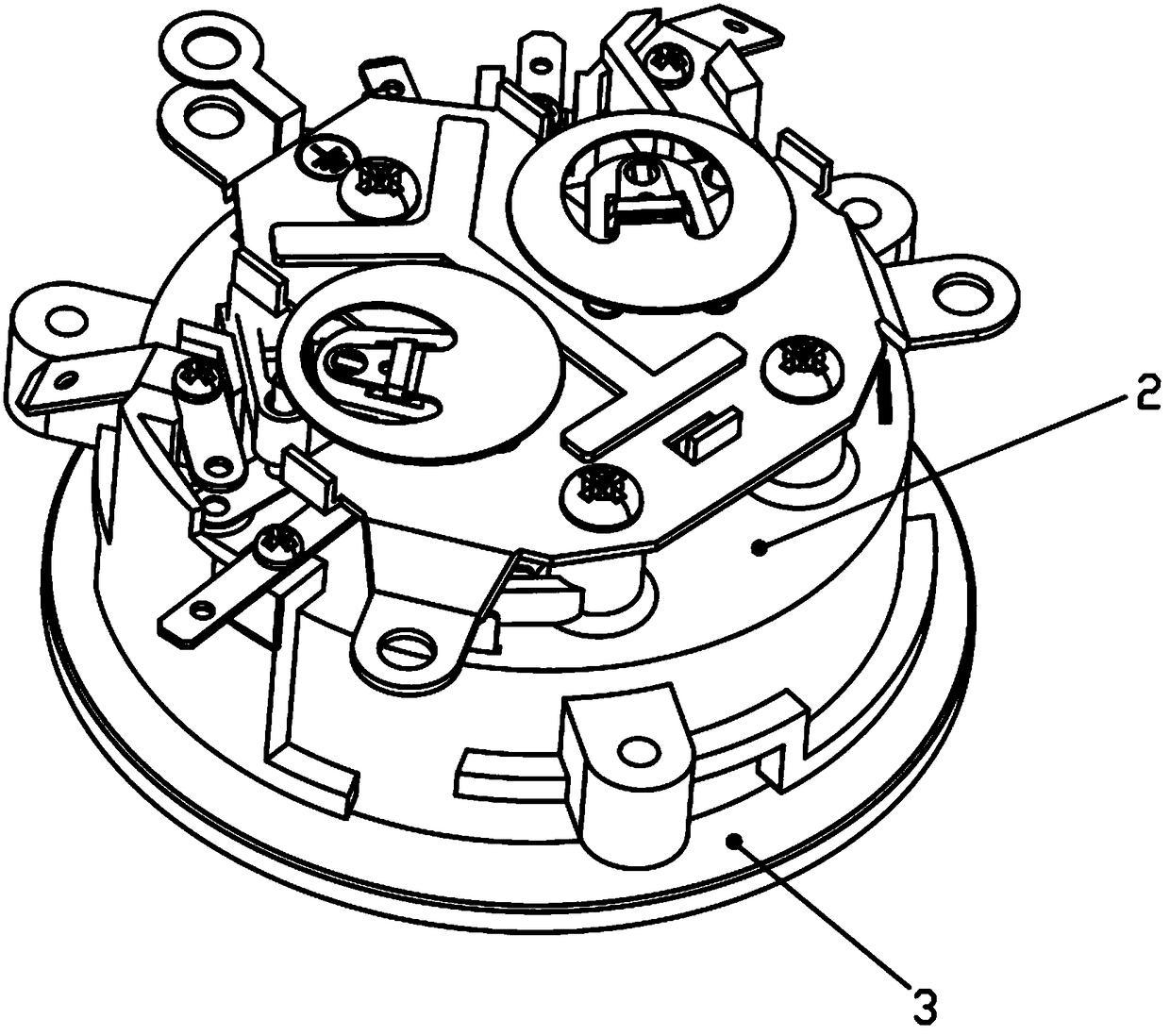
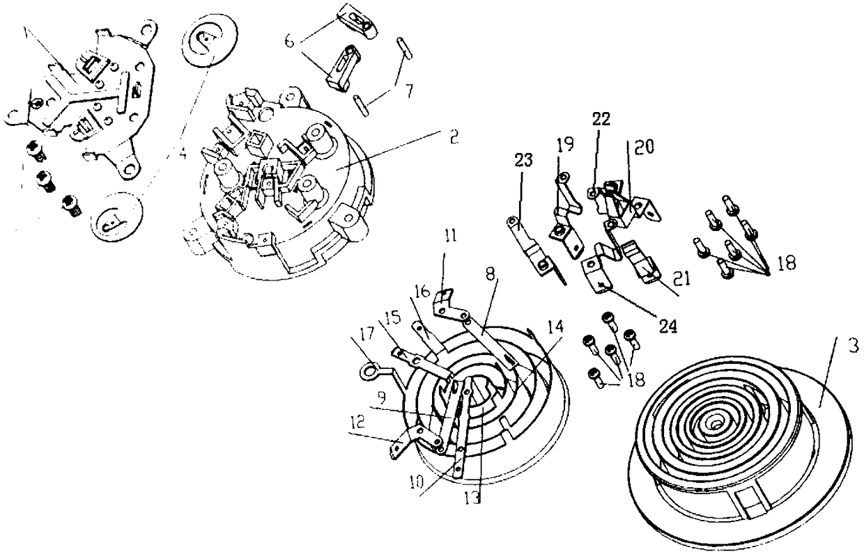
[0019] Such as Figure 1-Figure 3 As shown, the weight toothed coupler includes a connector 3 and an appliance input socket 2. The appliance input socket 2 is provided with a fixed iron plate 1, a thermal bimetal 4 and a fixing seat 6. The thermal bimetal The piece 4, the fixed iron plate 1 and the appliance input socket 2 are fixed and assembled in sequence. The appliance input socket 2 is also provided with a fixed seat 6 which is provided with movable holes and a porcelain rod top rod 7, The rod top rod 7 and the movable hole are movably cooperated, and the thermal bimetal sheet 4 is a mature prior art product, which will not be elaborated here.
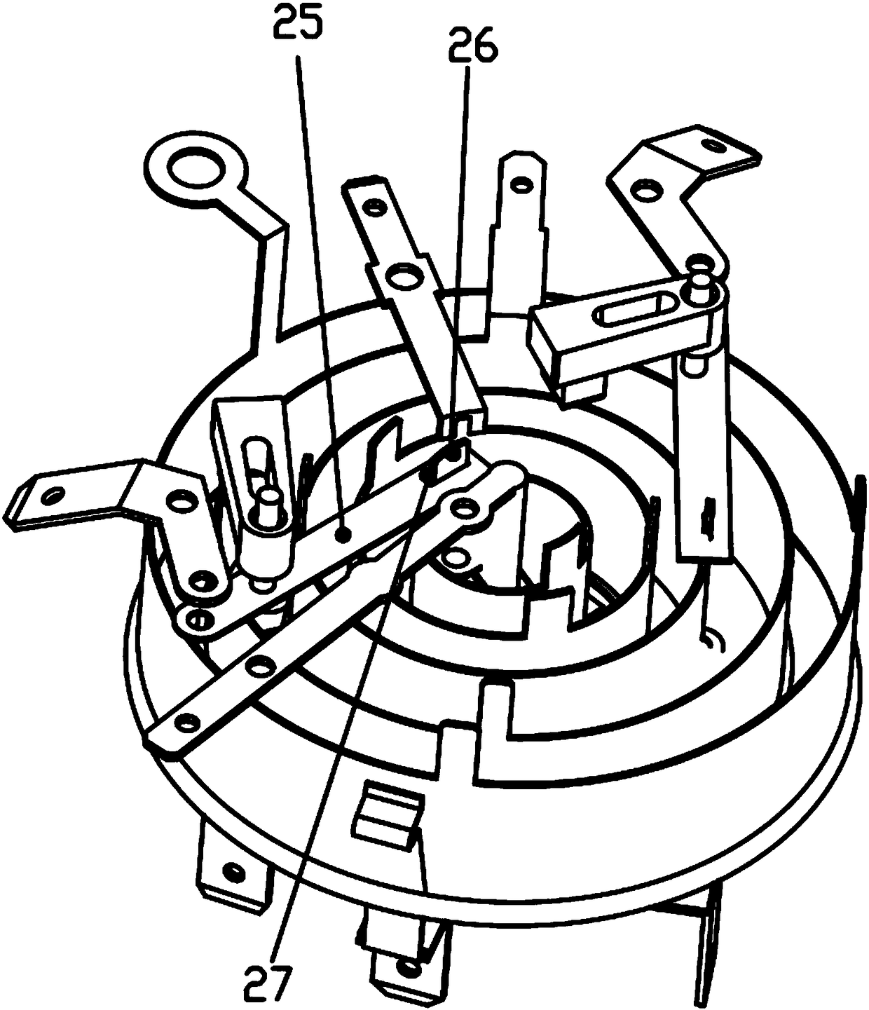
[0020] The appliance input socket 2 is provided with a first signal post 10, a second signal ring 15, a third signal ring 16, an N-pole conductive ring 14, an L-pole conductive ring 13, and a grounding ring 17. The first signal The post 10, the second signal ring 15 and the third signal ring 16 are provided with a terminal 25. The L-pole conductive ring 13 is provided with an L-pole movable spring 9 and an L-pole plug-in terminal 12 in sequence. The pole conductive ring 14 is sequentially provided with an N pole movable reed 8 and an N pole plug-in terminal 11, between the N pole movable reed 8 and the N pole plug-in terminal 11, the L pole movable reed 9 and the L pole The plug-in terminals 12 are in contact with each other, and the N-pole plug-in terminals 11 and L-pole plug-in terminals 12 are respectively fixedly assembled with the appliance input socket 2;
[0021] The thermal bimetal 4, the porcelain rod ejector 7 and the porcelain rod ejector 7 are each provided with two, the ceramic rod ejector 7 pushes the L pole movable reed 9 and the N pole through the thermal bimetal 4 respectively. Polar reed 8;
[0022] The housing is provided with an N pole reed 22, an L pole reed 23, a third signal reed 24, a second signal reed 19, a first signal reed 20, and a grounding reed 21. Between the second signal reed 19 and the second signal ring 15, between the L pole reed 23 and the L pole conductive ring 13, the N pole reed 22 and the N pole conductive ring 14, the first signal column 10 and the first signal spring The plates 20, the third signal reed 24 and the third signal ring 16, and the ground ring 17 and the ground reed 21 are all in contact with each other. The terminal of the third signal ring 16 is added to the traditional circuit structure. 25. Multi-path function to facilitate power input. The circuit connectors are arranged in the longitudinal direction, and are located in the housing of the corresponding appliance input socket 2 or connector 3 to avoid the misalignment of the opposite reeds and the contact points of the reeds. Displacement, causing no electricity to occur.
[0023] The first signal column 10, the second signal ring 15 and the third signal ring 16 are all integrated structures, which refer to the first signal column 10, the second signal ring 15, the third signal ring 16, and the ground ring 17 and their respective The terminal 25 is an integral structure.
[0024] The N-pole conductive ring 14 and the L-pole conductive ring 13 have socket ends 26, and the N-pole movable reed 8 and the L-pole movable reed 9 are respectively provided with socket holes 27, and the bearing The socket 27 is assembled with the socket end 26, and the socket end 26 is inserted into the socket socket 27 to facilitate installation and disassembly.
[0025] The L pole movable reed 9, the N pole movable reed 8, the second signal reed 19, and the third signal reed 24 are all welded with silver contacts. The silver contacts enhance the conductivity and the stability of the circuit connection. .
[0026] The terminal 25, the N-pole plug-in terminal 11 and the L-pole plug-in terminal 12 are respectively connected and fixed to the appliance input socket 2 by a first screw 18. The N-pole reed 22, the L-pole reed 23, and the first The three signal reeds 24, the second signal reeds 19, the first signal reeds 20 and the grounding reeds 21 are respectively connected and fixed to the connector 3 by the first screw 18, which is convenient for installation and removal.
[0027] The connector 3 and the appliance input socket 2 are sleeved and matched, so that the two planes are in relatively up and down contact, and the structural stability is enhanced.
[0028] The connector 3 is provided with a number of annular grooves for accommodating the first signal post 10, the second signal ring 15, the third signal ring 16, the N-pole conductive ring 14, the L-pole conductive ring 13, and the ground ring 17 respectively, which is convenient Install and protect related circuit connectors.
[0029] The fixed iron plate 1 and the appliance input socket 2 are connected and fixed by the second screw 5, which is convenient for installation and removal.
[0030] Working principle: The thermal expansion of the thermal bimetal 4 collides with the porcelain rod ejector rod 7, thereby driving the porcelain rod ejector rod 7 to push the L pole movable reed 9 and the N pole movable reed 8 apart, making the L pole movable reed 9 and The L pole plug-in terminal 12, the N pole movable reed 8 and the N pole plug terminal 11 are separated, the electrical circuit is disconnected, and the first signal ring, the second signal ring 15 and the third signal ring 16 are connected to their respective The terminal 25 is an integrated structure, which is different from the traditional side contact, which enhances the stability of the structure and performance, and ensures the stable contact with the reed contact point.
[0031] The beneficial effects of the present invention: the weight toothed coupler provided by the present invention has six connection terminals, in addition, the signal connection terminal and the signal conductive ring adopt a conjoined structure, which constitutes a reasonably structured electric weight toothed coupler, connector The L pole reed, N pole reed, second signal reed, and third signal reed are all installed with silver contacts. The contact mode of the input socket and the connector is upper and lower plane contact, and the performance is safe and reliable.
[0032] In the description of the present invention, it should be noted that the terms "center", "upper", "lower", "front", "rear", "left", "right", "vertical", "horizontal", The orientation or positional relationship indicated by "top", "bottom", "inner", "outer", etc. are based on the orientation or positional relationship shown in the drawings, and are only for the convenience of describing the present invention and simplifying the description, rather than indicating or implying The referred device or element must have a specific orientation, be configured and operated in a specific orientation, and therefore cannot be understood as a limitation of the present invention.

PUM

no PUM

Description & Claims & Application Information

We can also present the details of the Description, Claims and Application information to help users get a comprehensive understanding of the technical details of the patent, such as background art, summary of invention, brief description of drawings, description of embodiments, and other original content. On the other hand, users can also determine the specific scope of protection of the technology through the list of claims; as well as understand the changes in the life cycle of the technology with the presentation of the patent timeline. Login to view more.

Similar technology patents

Skateboard battery device

Owner:GUANGDONG TANJIN ELECTRONICS TECH CO LTD

Classification and recommendation of technical efficacy words

Why Eureka
Try Eureka