A kind of arc punching equipment and arc punching method at both ends of circular tube

A technology for punching arcs and round tubes, which is applied to arc punching equipment at both ends of round tubes and the field of punching arcs. It can solve problems such as poor machining accuracy, low processing efficiency, and arc openings that cannot be guaranteed to be orthogonal.

Active Publication Date: 2019-04-05
浙江亚奇工艺品股份有限公司
View PDF7 Cites 0 Cited by
  • Summary
  • Abstract
  • Description
  • Claims
  • Application Information

AI Technical Summary

Problems solved by technology

In the existing arc punching process, the processing is generally carried out manually, and the processing is carried out by the hand of the worker, and the processing efficiency is low. At the same time, after the processing of one end of the pipe is completed, before the other end of the processed pipe is punched, the pipe needs to be turned over and at the same time A 90-degree rotation is required. If the 90-degree rotation is performed manually, the arcs at both ends of the pipe cannot be guaranteed to be orthogonal, resulting in poor machining accuracy.

Method used


Image

  • A kind of arc punching equipment and arc punching method at both ends of circular tube
  • A kind of arc punching equipment and arc punching method at both ends of circular tube
  • A kind of arc punching equipment and arc punching method at both ends of circular tube

Examples


Embodiment Construction

[0026] The present invention will be further described in detail below in conjunction with the accompanying drawings and embodiments.

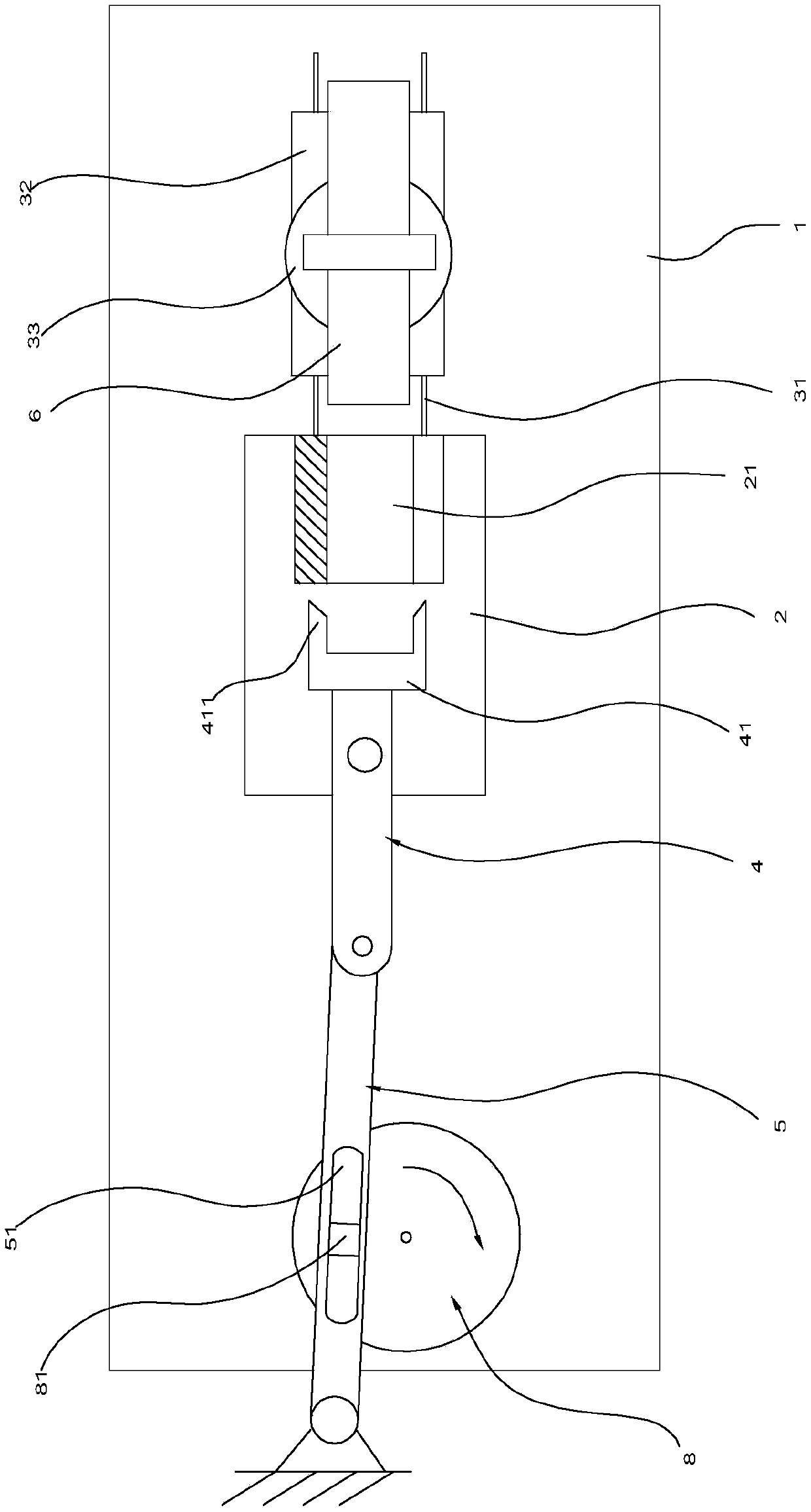
[0027] Such as Figures 1 to 5 As shown, the arc punching equipment at both ends of the round pipe in this implementation includes a platform 1, a feeding rotation mechanism and a toggle arc punching mechanism.

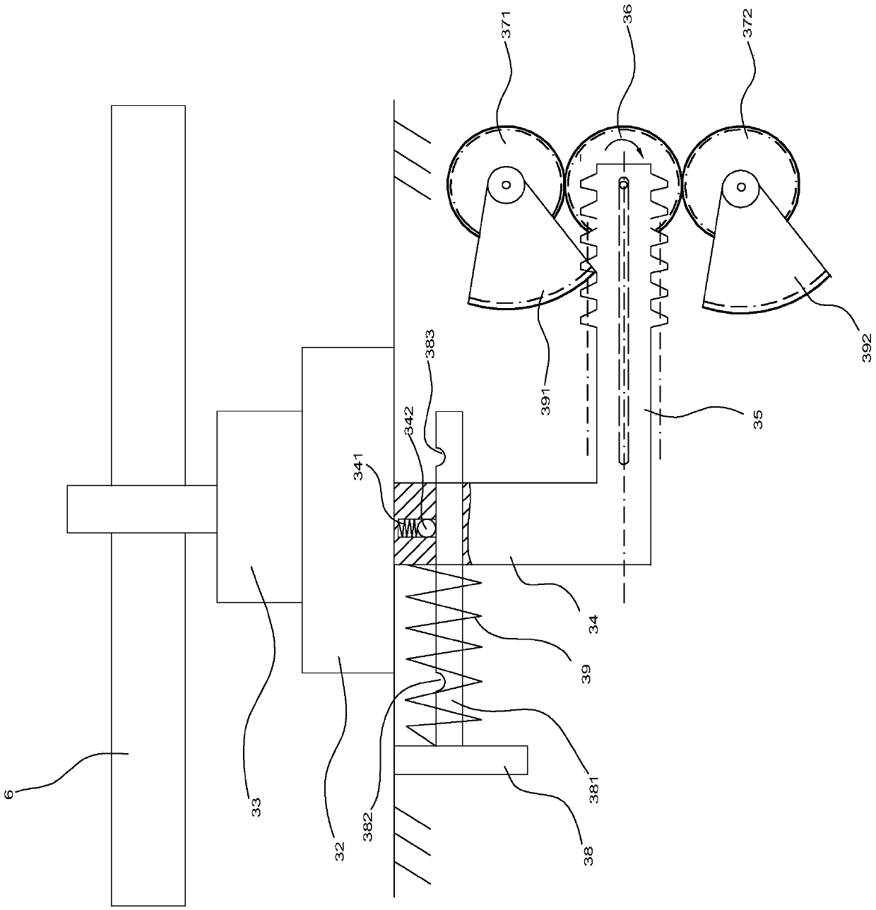
[0028]Among them, an arc punching seat 2 is arranged on the platform 1, and one end of the arc punching seat 2 is provided with a guide rail 31. The interior of the seat 2 is hollow, and a limit sleeve 21 is provided at the end of the punching seat 2 close to the feeding rotating mechanism. The feeding rotating mechanism includes a base 32 slidably arranged on the guide rail 31, and a rotating cylinder 33 arranged on the base 32. , the connecting block 34 that is arranged on the lower end surface of the base 32, the connecting rod 35 that is connected with the connecting block 34 and arranged horizontally, the driving gear 36, the dr...


PUM


Abstract

The invention discloses a device and a method for punching arcs on two ends of a circular pipe. The device comprises an arc punching seat, a feeding and rotating mechanism and a pulling and arc punching mechanism. A limiting sleeve is arranged in the arc punching seat; the feeding and rotating mechanism comprises a base, a rotary cylinder, a connecting block, a guiding pillar, a spring, a connecting rod, a drive gear and two driven gears; the pulling and arc punching mechanism comprises a rotary plate, a slide block, a drive rod, and an arc punching rod rotatably arranged in the arc punching seat; the rotary plate drives the drive rod to swing; and the drive rod drives the arc punching rod to swing. The arc punching method comprises the following steps: a pipe is clamped and limited in a clamping mechanism, the drive gear rotates, one fan-shaped gear drives one end of the pipe to be inserted into the limiting sleeve in the arc punching seat, the rotary plate rotates, the drive rod drives the arc punching rod to swing back and forth, a cutter carries out arc punching processing on two sides of one end of the pipe, the other fan-shaped gear drives the pipe to retreat, a rotary motordrives a worm to rotate, the worm drives a worm wheel to rotate at 90 degrees, the rotary cylinder drives the pipe to turn over at 180 degrees, and the other end of the pipe is subjected to arc punching processing.

Description

technical field [0001] The invention relates to the field of arc-striking machining at the end of pipe fittings, in particular to an arc-striking device at both ends of a round pipe and an arc-striking method thereof. Background technique [0002] In the prior art, it is often designed to perform arc punching on both ends of the pipe, for example, in bicycle processing. In the existing arc punching process, the processing is generally carried out manually, and the processing is carried out by the hand of the worker, and the processing efficiency is low. At the same time, after the processing of one end of the pipe is completed, before the other end of the processed pipe is punched, the pipe needs to be turned over and at the same time A 90-degree rotation is required. If the 90-degree rotation is performed manually, the arcs at both ends of the pipe cannot be guaranteed to be orthogonal, resulting in poor machining accuracy. [0003] For this reason, the Chinese invention w...

Claims


Application Information

Patent Timeline
Patent Type & Authority Patents(China)
IPC IPC(8): B21D31/00
CPCB21D31/005
Inventor 谢齐容
Owner 浙江亚奇工艺品股份有限公司
Why Eureka
Try Eureka