Arc punching device and arc punching method at both ends of a circular tube

A technology of arc punching and round pipe, which is applied in the field of arc punching machining at the end of pipe fittings, can solve the problems of inability to guarantee the orthogonality of the arc, low machining efficiency, poor machining accuracy, etc., and achieve automatic arc punching and blanking operations. , The effect of reducing labor intensity and improving machining accuracy

Active Publication Date: 2019-04-19
雷磊
View PDF5 Cites 0 Cited by
  • Summary
  • Abstract
  • Description
  • Claims
  • Application Information

AI Technical Summary

Problems solved by technology

In the existing arc punching process, the processing is generally carried out manually, and the processing is carried out by the hand of the worker, and the processing efficiency is low. At the same time, after the processing of one end of the pipe is completed, before the other end of the processed pipe is punched, the pipe needs to be turned over and at the same time A 90-degree rotation is required. If the 90-degree rotation is performed manually, the arcs at both ends of the pipe cannot be guaranteed to be orthogonal, resulting in poor machining accuracy.

Method used


Image

  • Arc punching device and arc punching method at both ends of a circular tube
  • Arc punching device and arc punching method at both ends of a circular tube
  • Arc punching device and arc punching method at both ends of a circular tube

Examples


Embodiment Construction

[0028] The present invention will be further described in detail below in conjunction with the accompanying drawings and embodiments.

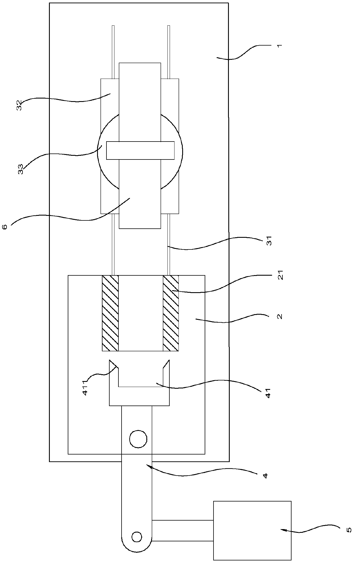
[0029] Such as Figures 1 to 7 As shown, the arc punching device at both ends of the round pipe in this implementation includes a platform 1, a feeding rotation mechanism and a toggle arc punching mechanism.

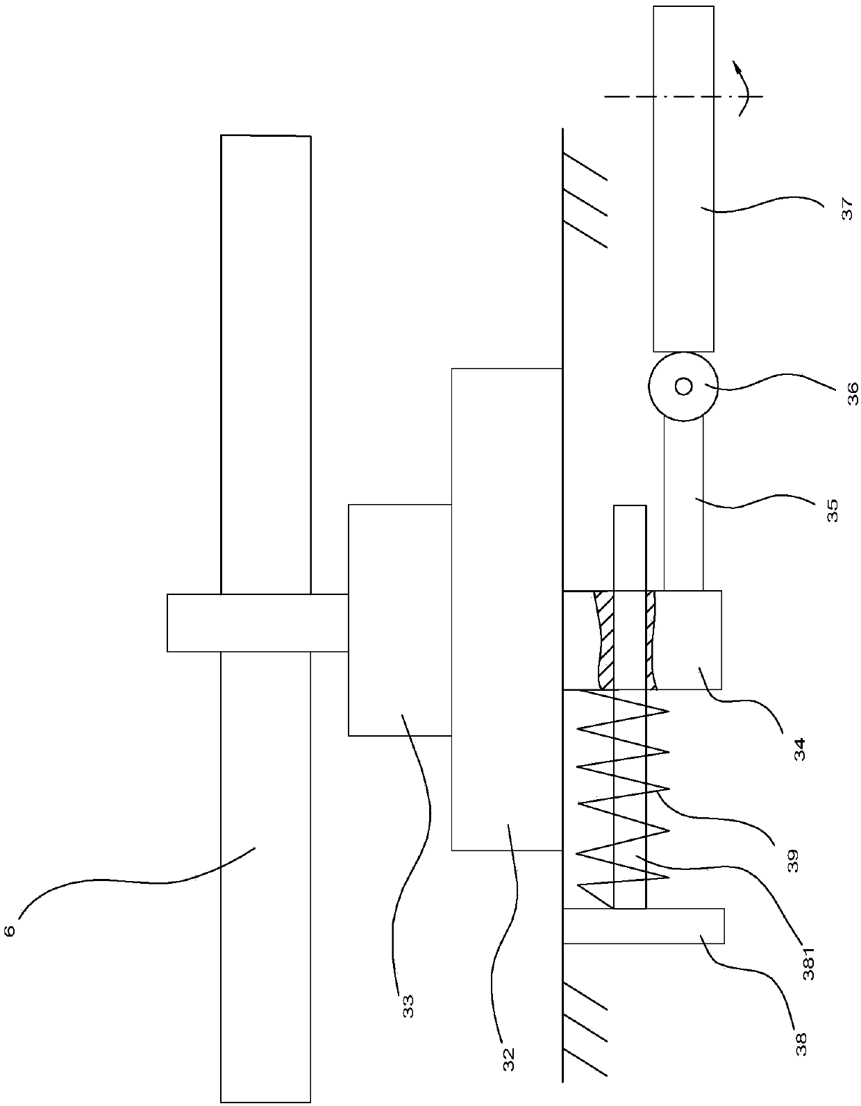
[0030]Among them, an arc punching seat 2 is arranged on the platform 1, and one end of the arc punching seat 2 is provided with a guide rail 31. The interior of the seat 2 is hollow, and a limit sleeve 21 is provided at the end of the punching seat 2 close to the feeding rotating mechanism. The feeding rotating mechanism includes a base 32 slidably arranged on the guide rail 31, and a rotating cylinder 33 arranged on the base 32. , the connecting block 34 that is arranged on the lower end surface of the base 32, the connecting rod 35 that is connected with the connecting block 34 and arranged transversely, the roller 36 that is arranged...


PUM


Abstract

The invention discloses an arc punching device for both ends of a circular tube and an arc punching method thereof. The arc punching device comprises an arc punching seat, a feeding rotating mechanism, and a pulling arc-punching mechanism; and a limiting sleeve is arranged in the arc punching seat, the feeding rotating mechanism comprises a base, a rotating cylinder, a connecting block, a roller,a spring, and a rotating cam, the pulling arc-punching mechanism comprises a cylinder body, an arc punching rod rotatably arranged in the arc punching seat, and a rotor and blades are arranged in thecylinder body. The arc punching method comprises the following steps that a pipe fitting is clamped and limited in a clamping mechanism, the rotating cam rotates, and one end of the pipe fitting is inserted into the limiting sleeve of the arc punching seat; the cylinder body is fed with oil, the rotor drives the arc punching rod to swing, and one side of one end of the pipe fitting is arc-punchedby cutters; the cylinder body is fed with oil in the backward direction, and the other side of one end of the pipe fitting is arc-punched by the cutters; and the feeding rotating mechanism exits, a rotating motor dives a worm to rotate, the worm drives a turbine ring to rotate by 90 degrees, the rotating cylinder drives the pipe fitting to overturn by 180 degrees, and the other end of the pipe fitting is arc-punched.

Description

technical field [0001] The invention relates to the field of arc-striking machining at ends of pipe fittings, in particular to an arc-striking device at both ends of a round pipe and an arc-striking method thereof. Background technique [0002] In the prior art, it is often designed to perform arc punching on both ends of the pipe, for example, in bicycle processing. In the existing arc punching process, the processing is generally carried out manually, and the processing is carried out by the hand of the worker, and the processing efficiency is low. At the same time, after the processing of one end of the pipe is completed, before the other end of the processed pipe is punched, the pipe needs to be turned over and at the same time A 90-degree rotation is required. If the 90-degree rotation is performed manually, the arcs at both ends of the pipe cannot be guaranteed to be orthogonal, resulting in poor machining accuracy. [0003] For this reason, the Chinese invention with...

Claims


Application Information

Patent Timeline
Patent Type & Authority Patents(China)
IPC IPC(8): B21D28/00B21D28/02B21D28/14B21D43/00B21D43/04B21D43/14
CPCB21D28/002B21D28/02B21D28/14B21D43/003B21D43/04B21D43/14
Inventor 谢齐容
Owner 雷磊
Why Eureka
Try Eureka