Integrated automatic punching and flanging machine for valve pipes

An automatic punching and all-in-one machine technology, applied in the direction of feeding device, positioning device, storage device, etc., can solve the problems of high manufacturing cost, low degree of automation, low production efficiency, etc., and achieve reduced labor costs and stable operation Good, the effect of reducing processing costs

Inactive Publication Date: 2015-05-27
ZHUJI RUN TUO MECHANICAL AUTOMATION TECH
View PDF8 Cites 14 Cited by
  • Summary
  • Abstract
  • Description
  • Claims
  • Application Information

AI Technical Summary

Problems solved by technology

[0004] Although the above-mentioned scheme has improved some problems of the prior art to a certain extent, the scheme still has at least the following defects: unreasonable design, high product scrap rate and low production efficiency, low degree of automation and failure to meet the high requirements of the product. Quality requirements, secondly, high manufacturing costs and poor practicability

Method used


Image

  • Integrated automatic punching and flanging machine for valve pipes
  • Integrated automatic punching and flanging machine for valve pipes
  • Integrated automatic punching and flanging machine for valve pipes

Examples


Embodiment Construction

[0034] The present invention will be described in further detail below in conjunction with the accompanying drawings and specific embodiments.

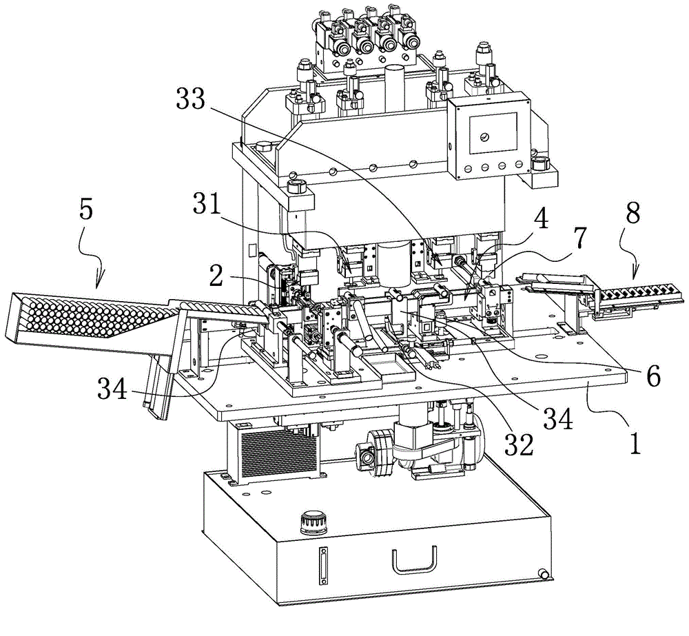
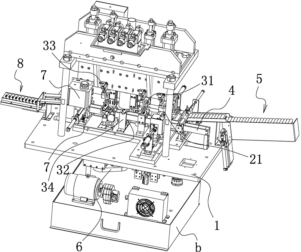
[0035] Such as Figure 1-2 and Figure 13 As shown, the valve tube automatic punching and flanging integrated machine includes a frame 1, on which a large hole punching device 2 for processing three large holes a1 on the workpiece a is sequentially arranged, and a large hole punching device 2 for processing three large holes a1 on the workpiece a. The small hole punching device 31 of the small hole a2 opposite to the middle big hole a1, the annealing device 32 that anneals the workpiece a, and the flanging hole device 33 that forms the flanging outside the small hole a2 are arranged on the frame 1. There are some tube racks 34 that are arranged one by one correspondingly with punching large hole device 2, punching small hole device 31, annealing device 32 and flanging hole device 33, and described frame 1 is also provided with for pl...


PUM


Abstract

The invention belongs to the technical field of mechanical equipment and particularly relates to an integrated automatic punching and flanging machine for valve pipes. According to the integrated automatic punching and flanging machine for the valve pipes, the technical problems of low automation degree and poor product processing quality in the prior are solved. The integrated automatic punching and flanging machine for the valve pipes comprises a machine frame, wherein a large-hole punching device, a small-hole punching device, an annealing device and a hole flanging device are sequentially arranged on the machine frame; the large-hole punching device punches three large holes in a workpiece; the small-hole punching device punches a small hole opposite to the middle large hole in the workpiece; the annealing device anneals the workpiece; the hole flanging device flanges the outer side of the small hole; a plurality of pipe placement frames in one-to-one correspondence to the large-hole punching device, the small-hole punching device, the annealing device and the hole flanging device are arranged on the machine frame; a material transferring mechanism used for sequentially transferring the workpiece on all the pipe placement frames to enable the large-hole punching device, the small-hole punching device, the annealing device and the hole flanging device to sequentially process the workpiece is further arranged on the machine frame. The integrated automatic punching and flanging machine for the valve pipes has the advantages that the processing quality of products is improved, and the automation degree is high.

Description

technical field [0001] The invention belongs to the technical field of mechanical equipment, and in particular relates to an automatic punching and flanging integrated machine for valve tubes. Background technique [0002] The structure of the valve pipe is tubular, with three large holes and a small hole corresponding to the middle large hole on the valve pipe, and the opening of the small hole is flanged. At present, the existing processing methods are as follows: large holes, small holes and hole flanging are respectively processed and manufactured by three different equipments. Although such a processing method can meet the production requirements to a certain extent, the production efficiency of this scheme is low, the production cycle is long, the degree of automation is low, and it cannot meet the large-scale production requirements of enterprises. At present, in order to improve production efficiency and reduce labor costs, many enterprises independently manufacture...

Claims


Application Information

Patent Timeline
Patent Type & Authority Applications(China)
IPC IPC(8): B21D35/00B21D28/28B21D43/05B21D45/06
Inventor 俞才王
Owner ZHUJI RUN TUO MECHANICAL AUTOMATION TECH
Why Eureka
Try Eureka