
Assembling device and method of splined sleeve gear coupling of aircraft engine

A technology of aero-engines and gear couplings, which is applied in the direction of hand-held tools and manufacturing tools, can solve the problems of high manufacturing cost of components, low assembly efficiency, and long processing cycle, so as to shorten the assembly cycle, avoid damage, improve safety effect

Active Publication Date: 2018-06-19
AECC SICHUAN GAS TURBINE RES INST
View PDF5 Cites 0 Cited by
  • Summary
  • Abstract
  • Description
  • Claims
  • Application Information

AI Technical Summary

Problems solved by technology

Due to the characteristics of the aero-engine industry, such as small production batches, high component manufacturing costs, long processing cycles, and small stock of spare parts, once structural damage occurs, the assembly and disassembly cycle of the engine will be greatly increased
For military engines in service, the extension of the overhaul cycle will seriously affect the integrity rate of military equipment and directly affect the combat effectiveness of aviation arms
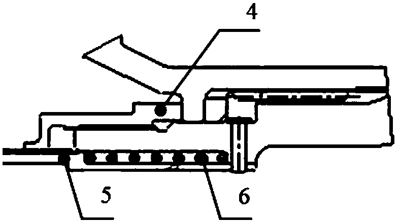
In addition, in the existing method, because the circumferential position of the shaft end nut [4] cannot be seen during the assembly process, it takes many attempts to make the spline of the inner bush [5] smoothly move from the shaft end nut [4] to the inner spline. Pop-up, so the assembly efficiency is low

Method used


Image

  • Assembling device and method of splined sleeve gear coupling of aircraft engine
  • Assembling device and method of splined sleeve gear coupling of aircraft engine
  • Assembling device and method of splined sleeve gear coupling of aircraft engine

Examples


Embodiment Construction

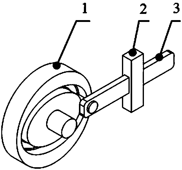
[0029] The present invention will be described in further detail below in conjunction with the accompanying drawings of the description, please refer to Figure 1~5 .

[0030] The driving component [1] is located inside the device, and its main function is to realize the telescopic movement of the bolt component [3] according to a predetermined rule, and the core part is designed in the shape of a groove.

[0031] The housing component [2] is located outside the device, and its main function is to realize the assembly and disassembly of the shaft end nut [4], and at the same time ensure that the spring [6] is in a compressed state when the device is installed on the engine, and the shaft end nut [4] and The engagement splines of the inner liner [5] are separated, and the dead bolt assembly [3] can be freely expanded and contracted. The housing assembly has a guide hole for controlling the direction of the deadbolt assembly [3]. The housing assembly [2] has external splines t...


PUM


Abstract

The invention relates to an assembling device and method of a splined sleeve gear coupling of an aircraft engine. The structure of the device is shown in fig.1. The device mainly comprises a driving assembly (1), a housing assembly (2) and a spring bolt assembly (3). With the adoption of the device, the splined sleeve gear coupling of the aircraft engine can be safely and reliably assembled, and the engine is prevented from damage caused by assembling the structure through a general device; a device for indicating the rotating angle of a shaft end nut (4) is provided. The invention also relates to a method for assembling the splined sleeve gear coupling. With the adoption of the device and method, the assembling position of the shaft end nut (4) can be accurately determined; an inner bushing (5) spline can be smoothly sprung out from an inner spline of the shaft end nut (4) in one time. With the adoption of the method, the assembling efficiency of the splined sleeve gear coupling can be improved, and the assembling circle is reduced; and meanwhile the engine assembling quality is ensured; and the quality risk of damage of parts and assemblies of the engine in the splined sleeve gear coupling assembling process can be obviously reduced.

Description

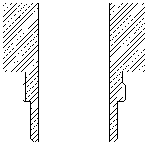
technical field [0001] The invention belongs to the technical field of aero-engine assembly, and in particular relates to an aero-engine spline bushing gear coupling assembly device and method. Background technique [0002] The spline sleeve gear coupling structure is widely used in the industry due to its small number of parts, high structural reliability and light weight. However, the assembly and disassembly of the structure has always been a technical difficulty in the industry. Because the spring [6] needs to be kept in a compressed state during the assembly and disassembly process, at this time the shaft end nut [4] is separated from the engaging spline of the inner bush [5], and at the same time, the shaft end nut [4] is rotated with a large torque to It is tightened or unscrewed. Taking a medium-thrust engine as an example, the torque is generally between 1000N·m and 3000N·m. More adoption in the industry image 3 The shown front end has the device of spline and b...

Claims


Application Information

Patent Timeline
Patent Type & Authority Applications(China)
IPC IPC(8): B25B27/14
Inventor 朱小海王良君王力周丽赵勇胡兴强
Owner AECC SICHUAN GAS TURBINE RES INST
Learn More