[0019] In order to make the object, technical solution and advantages of the present invention clearer, the present invention will be further described in detail below in conjunction with the accompanying drawings. It is only stated here that the words for directions such as up, down, left, right, front, back, inside, and outside that appear or will appear in the text of the present invention are only based on the accompanying drawings of the present invention, and are not specific to the present invention. limited.
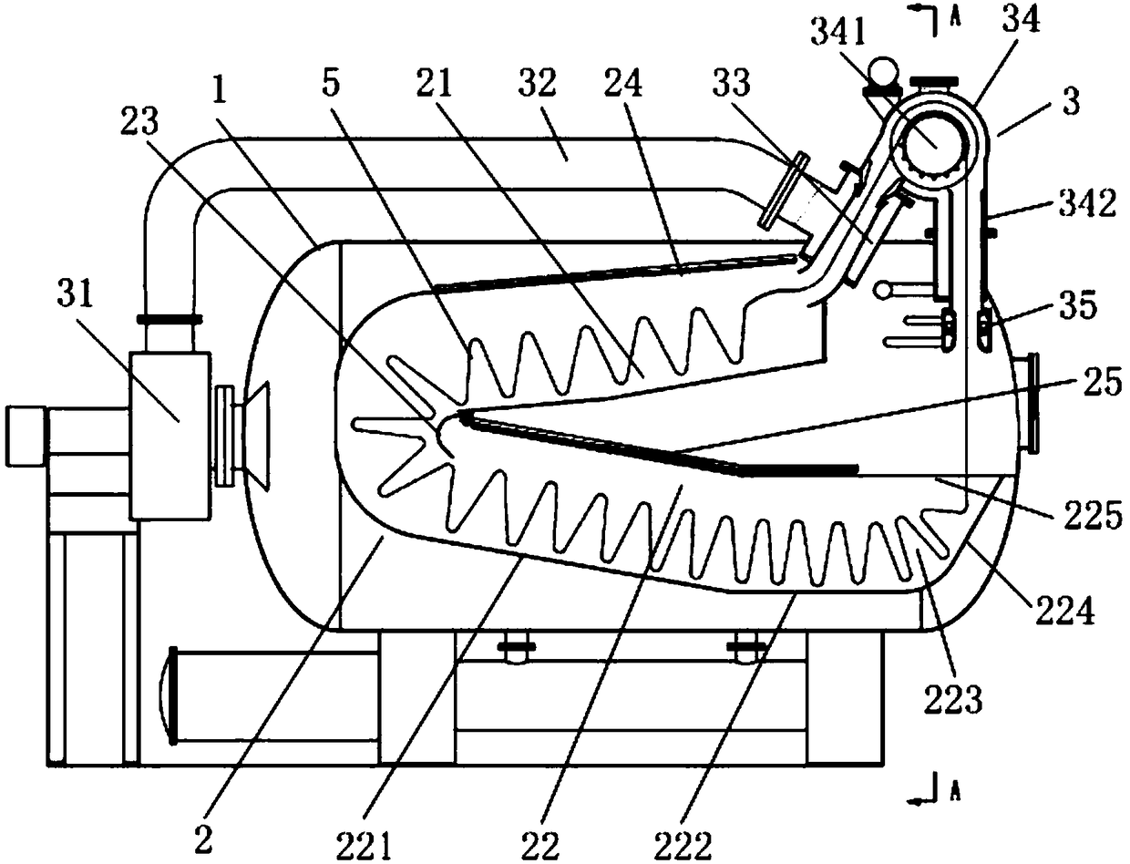
[0020] like figure 1 As shown, the first embodiment of the present invention provides an axially inclined high-temperature gas-liquid dyeing machine, including a main cylinder body 1 and a dyeing and finishing mechanism 3 for fabric dyeing and finishing. A cloth storage tank 2 is provided. The dyeing and finishing mechanism 3 includes a blower fan 31, an air duct 32, an air flow nozzle 33, a cloth lifting mechanism 34 and a front dye solution nozzle 35. The fan 31 is connected with the air flow nozzle 33 through the air duct 32, and the front dye solution The nozzle 35 is arranged on the feed side of the cloth lifting mechanism 34 , and the air flow nozzle 33 is arranged on the discharge side of the cloth lifting mechanism 34 .
[0021] Specifically, the cloth storage tank 2 includes an upwardly inclined chute 21 and a downwardly inclined chute 22 axially arranged in the main cylinder body 1, the upper end of the upwardly inclined chute 21 is close to the air nozzle 33, and the upwardly inclined chute 21 is close to the air nozzle 33. The chute 21 and the downward chute 22 are connected end to end. After the fabric is released from the dyeing and finishing mechanism 3, it slides obliquely downward from the right side to the left side of the main cylinder 1 from the upper end of the upward chute 21, and then enters the downward slant. The groove 22 slides obliquely downward from the left side of the main cylinder 1 to directly below the dyeing and finishing mechanism 3, and is drawn by the dyeing and finishing mechanism 3 to re-enter the dyeing and finishing mechanism 3 to realize the fabric dyeing and finishing cycle.
[0022] According to the present invention, the fabric in the downward inclined chute 22 of the main cylinder body 1 is lifted by the cloth lifting mechanism 34, passes through the pre-dye liquid nozzle 35, is pulled by the air flow nozzle 33, and falls into the main cylinder body 1 and slides downward in the axial direction. Groove 22 slides under the action of gravity component force, and falls in the descending chute 22 of main cylinder 1 again through turning to complete a cycle with this. The fabric is a cloth loop formed by connecting end to end, and can complete the required number of cycles according to the process setting requirements to achieve the dyeing process of the fabric. During the sliding process of the fabric in the axially inclined cloth storage tank 2 of the main cylinder body 1, it is mainly affected by the component force of its own gravity, and the force of mutual extrusion is relatively small. Not only is the fabric easy to expand and contract freely, but also the stacking state is orderly. Therefore, creases formed by mutual extrusion of fabrics are avoided, and at the same time, the fabric capacity of the main cylinder body 1 with the same volume can be effectively increased to improve production capacity.
[0023] Preferably, the cloth lifting mechanism 34 includes a cloth lifting roller 341 and a cloth lifting roller housing 342; the pre-dye liquid nozzle 35 is arranged in front of the cloth lifting roller 341; the rear air flow nozzle 33 is arranged at the After the cloth lifting roller 341. The end of the upward inclined chute 21 is provided with a corner adjustment plate 23, one end of which is hinged to the lower end of the upward inclined chute 21, and can swing a predetermined angle under the drive of a driving mechanism (not shown in the figure). The driving mechanism can be a common manual worm gear reducer, pneumatic cylinder or hydraulic cylinder, one end of which is connected to the angle adjustment plate 23, and the other end is connected to the upward inclined chute 21, and the rotation angle adjustment plate 23 is driven to swing by its own telescopic angle. The corner adjusting plate 23 has an arc-shaped surface, which is beneficial to the smooth movement of the fabric.
[0024] Preferably, the upper inclined chute 21 and the lower inclined chute 22 are provided with segmented and slidable cover plates, such as the upper cover plate 24 located on the upper inclined chute 21 and the lower inclined chute 22 Upper lower cover plate 25 runs out to stop sliding fabric. The inclined angles of the upward inclined chute 21 and the downward inclined chute 22 can be adjusted respectively, so as to be suitable for the inclined sliding speed of different fabric varieties and ensure smooth sliding.
[0025] Preferably, the descending chute 22 includes a slanting segment 221, a horizontal segment 222 and a converging segment 223 arranged in sequence, the slanting segment 221 is connected to the sloping chute 21 for transferring the fabric by gravity, so The horizontal section 222 is used for the interaction between the dye liquor and the fabric. The converging section 223 is provided with an arc-shaped guide surface 224 at the end, and an opening 225 is provided at the top, and the opening 225 is opposite to the dyeing and finishing mechanism 3 . Through the three-stage fabric treatment of the downward inclined chute 22, the running direction of the fabric can be changed smoothly, and the mutual pressure of the fabric is also more stable, preventing the fabric from concentrating and piling up at a certain point.
[0026] The working principle of this oblique high-temperature gas-liquid dyeing machine is as follows: the fabric 5 is lifted by the cloth lifting mechanism 34, passes through the front dyeing liquid nozzle 35, is pulled by the air flow nozzle 33, and falls into the upward inclined chute 21 of the main cylinder body 1 During the process, it slides down under the action of gravity component, and falls into the descending chute 22 of the main cylinder body 1 through turning, so as to complete a cycle. The fabric is a cloth loop formed by connecting end to end, and can complete the required number of cycles according to the process setting requirements to achieve the dyeing process of the fabric. When the fabric slides down in the inclined sliding cloth storage tank 2, it is mainly affected by its own gravity component, and the force of mutual extrusion is small. Not only is the fabric easy to expand and contract freely, but also the stacking state is orderly, preventing creases produce.
[0027] combine figure 2 , according to the second embodiment of the present invention, different from the single cloth storage tank 2 set in the main cylinder 1 in the first embodiment, in this embodiment, there are two groups of the cloth storage tanks (2a, 2b), which are symmetrical It is arranged on the left and right sides of the main cylinder body 1 and is separated by a partition plate 4 . The partition plate 4 is axially arranged at the center of the main cylinder body 1 and vertically divides the main cylinder body 1 into left and right parts. Each group of cloth storage tanks 2 is provided with independent pre-dye solution nozzles 35 and air flow nozzles 33, and the same cloth lifting mechanism 34 drives the fabric to circulate.
[0028] Adopting this embodiment, compared with the first embodiment, it has a higher utilization rate of the main cylinder body 1. When dyeing and finishing narrower fabrics 5, a single cloth storage tank 2 can be used for dyeing and finishing, saving dye liquor; Two cloth storage tanks 2 can work simultaneously to improve efficiency. The two cloth storage tanks 2 are driven by the same cloth lifting mechanism 34, which simplifies the structure.
[0029] The above disclosure is only a preferred embodiment of the present invention, which certainly cannot limit the scope of rights of the present invention. Therefore, equivalent changes made according to the claims of the present invention still fall within the scope of the present invention.