Tool for ultrasonic-assisted brazing filler metal spreading

An ultrasonic and tooling technology, which is applied in the field of tooling for ultrasonic-assisted solder spreading, can solve problems such as easy deviation, and achieve the effects of convenient operation, small footprint, and easy installation and disassembly

Active Publication Date: 2020-06-30
HENAN UNIV OF SCI & TECH
View PDF12 Cites 0 Cited by
  • Summary
  • Abstract
  • Description
  • Claims
  • Application Information

AI Technical Summary

Problems solved by technology

[0006] The purpose of the present invention is to provide a tooling for ultrasonic-assisted solder spreading, which solves the problem that the samples or workpieces to be welded are easily shifted when ultrasonic-assisted solder spreading is used in the prior art

Method used


Image

  • Tool for ultrasonic-assisted brazing filler metal spreading
  • Tool for ultrasonic-assisted brazing filler metal spreading
  • Tool for ultrasonic-assisted brazing filler metal spreading

Examples


Embodiment 2

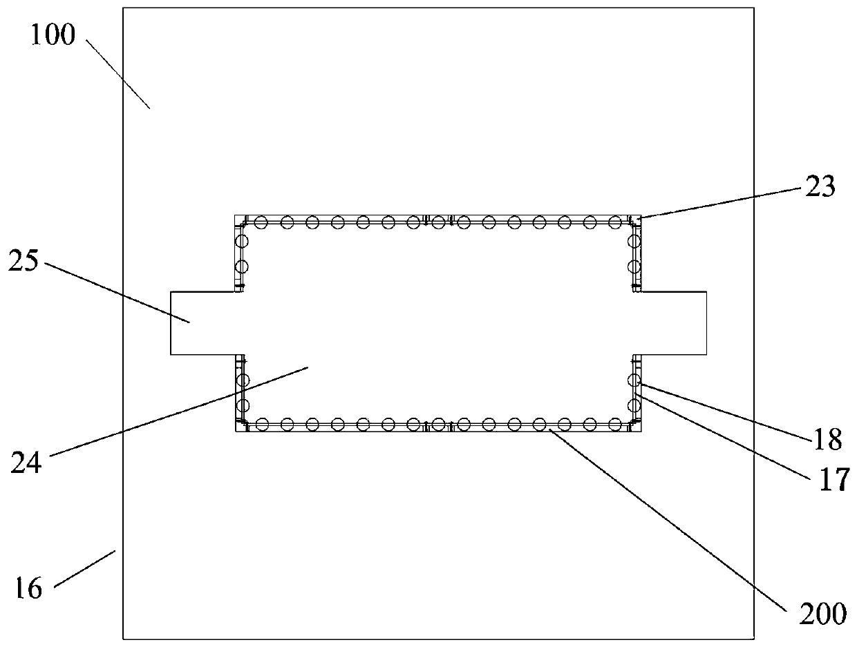
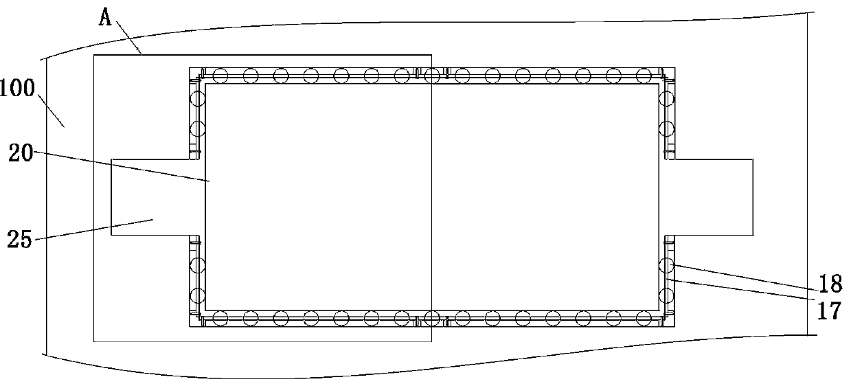
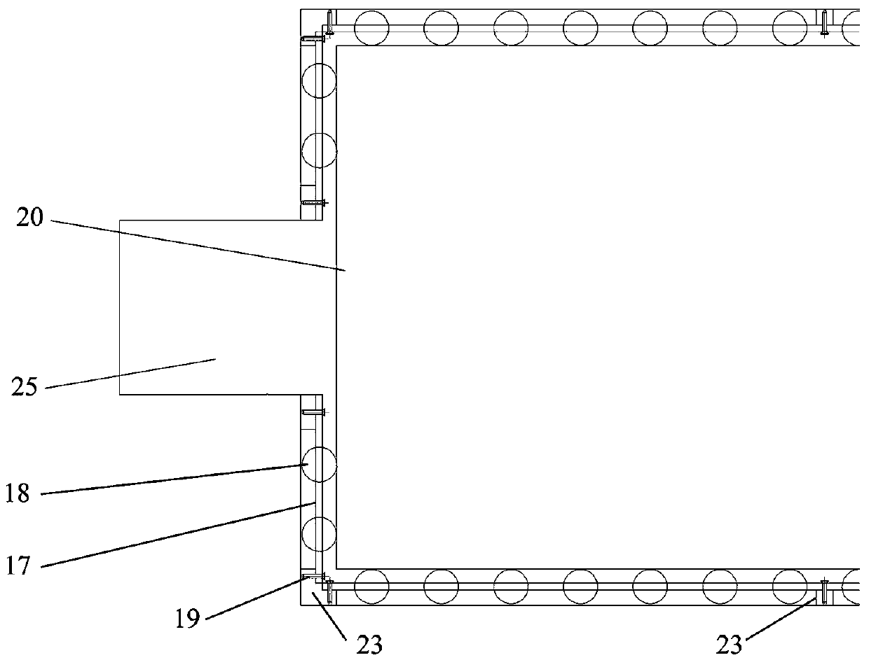
[0072] The difference between this embodiment and Embodiment 1 is that in Embodiment 1, the rolling body cage 17 is a strip-shaped flat plate structure, and the rolling body cage 17 is provided with a circular positioning hole 22, and the rolling body 18 is aligned with the empty space. The inner side wall of the chamber 21 is movably arranged in the positioning frame of the rolling element 18 in the vertical direction; and in the present embodiment, the structure of the rolling element cage 17 is similar to that of the deep groove ball bearing cage, but it is a linear structure. The hole structure confines the rolling body 18 in the form of a sphere, which can only rotate. Meanwhile, in order to avoid friction between the inner wall of the cavity 21 and the rolling element 18 , there is a space between the rolling element 18 and the inner wall of the cavity 21 .

Embodiment 3

[0074] The difference between this embodiment and Embodiment 1 is that in Embodiment 1, the positioning hole 22 on the rolling element cage 17 is a circular equal-diameter through hole, while in this embodiment, the positioning hole 22 on the rolling element cage 17 is The positioning hole 22 is a spherical hole, and the diameter of one end of the spherical hole close to the tooling main body 100 is larger than the diameter of the other end. The rolling element 18 is loaded from the large diameter end of the spherical hole, and one side is matched with the inner wall of the cavity 21. The other side is matched with the hole wall of the spherical hole.

[0075] Certainly, in other embodiments, the spherical hole may also be a tapered hole.

Embodiment 4

[0077] The difference between this embodiment and Embodiment 1 is that the rolling body 18 in Embodiment 1 is a sphere, while in this embodiment, the rolling body 18 is a cylinder. Correspondingly, the positioning hole 22 on the positioning frame of the rolling body 18 is Rectangular hole, the axis of rotation of the rolling element 18 extends in the horizontal direction.


PUM


Abstract

The invention relates to ultrasonic-assisted brazing filler metal spreading, in particular to a tool for ultrasonic-assisted brazing filler metal spreading. The tool for ultrasonic-assisted brazing filler metal spreading comprises a tool body, a rolling and guiding assembly, a rolling body positioning frame and rolling bodies. The rolling and guiding assembly is arranged on the tool body and comprises the rolling body positioning frame and the rolling bodies; positioning holes are formed in the rolling body positioning frame; the rolling bodies are arranged in the positioning holes; the positioning holes are used for enabling the rolling bodies to be distributed at intervals in the horizontal direction and provided with horizontal rotation axes; the rolling bodies surround to form a base metal holding space for placing base metal and limiting the base metal along the horizontal direction; one sides, facing the base metal holding space, of the rolling bodies are protruded out of a rolling body holder; the rolling bodies are in rolling fit with the vertical side face of the base metal along the vertical direction, so that the base metal is arranged on the tool body in a guiding way along the vertical direction. According to the scheme, the problem that in the prior art, a sample or a workpiece to be welded is easy to deviate when adopting ultrasonic-assisted brazing filler metalspreading is solved.

Description

technical field [0001] The invention relates to the use of ultrasonic waves to assist the spreading of solder, in particular to a tool for ultrasonically assisted spreading of solder. Background technique [0002] Good wetting between the solder and the base metal is the basis for obtaining high-quality brazed joints. Wetting is the premise of spreading. Only when the solder wets the base metal can it spread on the base metal and form a good brazing joint. Therefore, it is necessary to accurately analyze the solder spreading process to explore the solder wetting mechanism, so as to achieve the purpose of improving the solder wettability. The essence of solder wettability testing is to measure the wetting angle between solder and base metal, mainly by means of wetting angle tester, wetting balance method, wetting and spreading test, dipping method and other methods. [0003] The wetting angle tester can be used to directly evaluate the wettability of solder in real time, bu...

Claims


Application Information

Patent Timeline
Patent Type & Authority Applications(China)
IPC IPC(8): B23K1/06B23K3/08
CPCB23K1/06B23K3/087
Inventor 张柯柯尹宸翔张刘宇钟素娟吴婉吴咏锦王冰莹赵景申
Owner HENAN UNIV OF SCI & TECH
Why Eureka
Try Eureka