A kind of transportation and embedding equipment for utility poles

A technology for electric poles and equipment, which is applied in the field of transportation and embedding equipment, and can solve problems such as inaccurate installation

Active Publication Date: 2020-06-02
山东银顺奔彭车业有限公司
View PDF7 Cites 0 Cited by
  • Summary
  • Abstract
  • Description
  • Claims
  • Application Information

AI Technical Summary

Problems solved by technology

[0006] In order to overcome the disadvantages that the utility pole needs to be transported twice to reach the required installation position and cannot be accurately installed to the required installation point during installation, the present invention aims to The technical problem to be solved is to provide a kind of transportation and embedding equipment for electric poles that can make the electric poles to the required installation position without secondary transportation, and can be accurately installed on the required installation points during installation.

Method used


Image

  • A kind of transportation and embedding equipment for utility poles
  • A kind of transportation and embedding equipment for utility poles
  • A kind of transportation and embedding equipment for utility poles

Examples


Embodiment 1

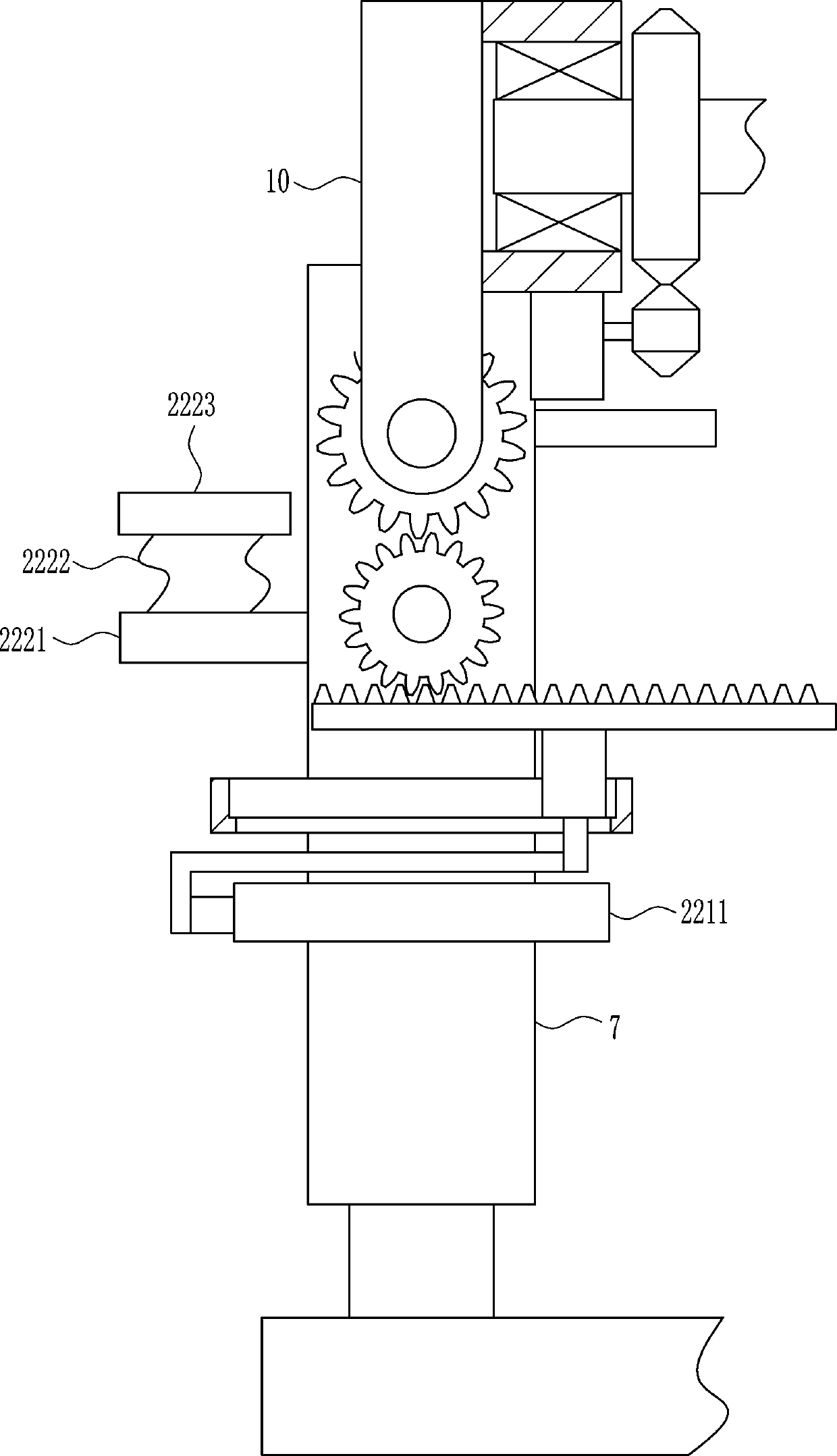
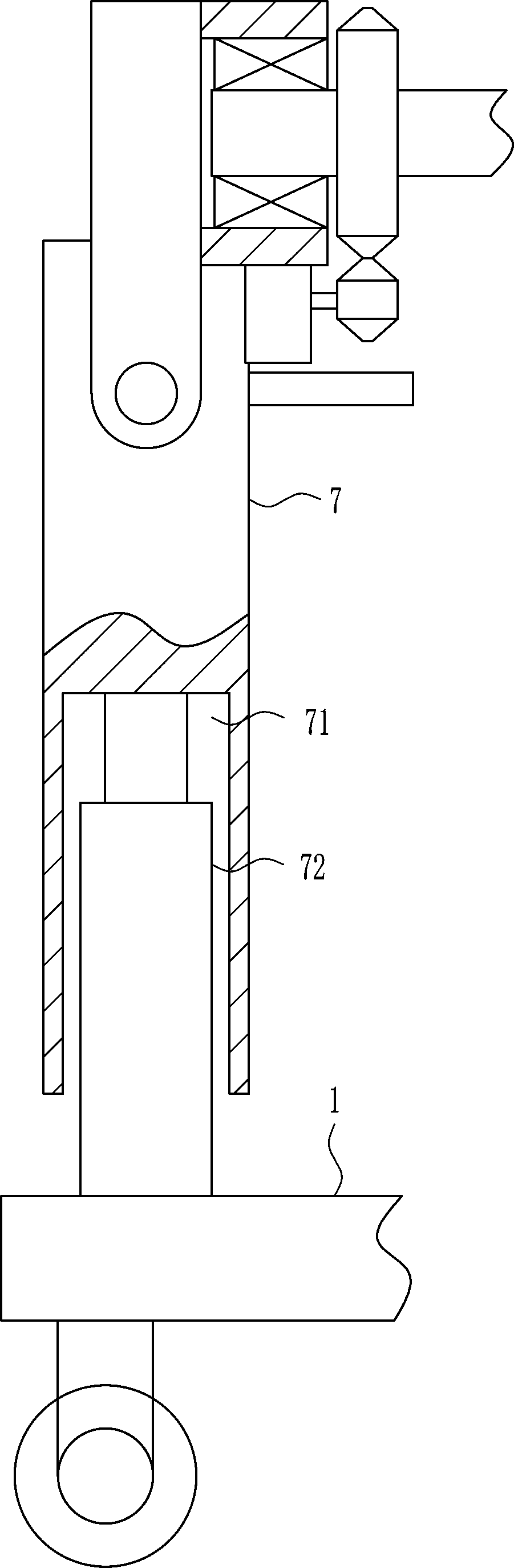
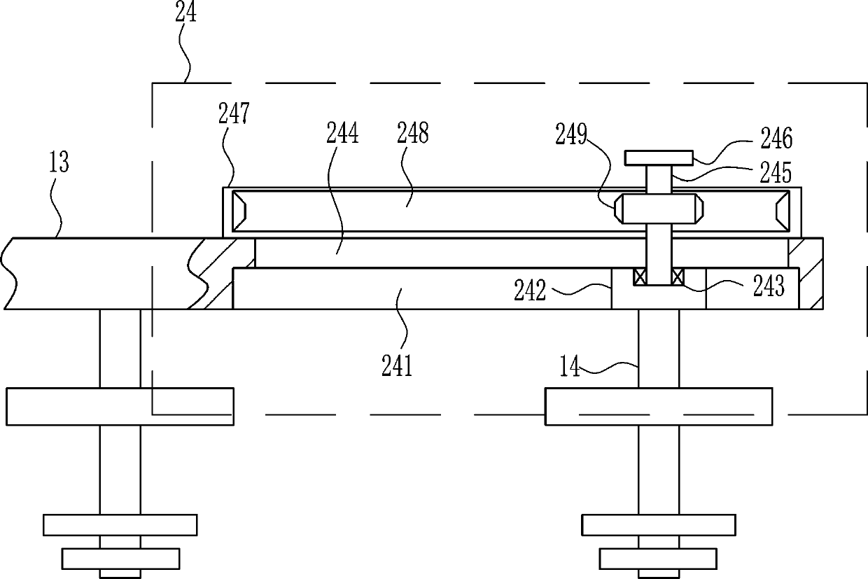
[0035] A kind of transportation and embedding equipment for utility poles, such as Figure 1-8 As shown, it includes a bottom plate 1, a bracket 2, a wheel shaft 3, a tire 4, a fixed plate 5, a placement plate 6, a support plate 7, a gear lever 8, a first rotating shaft 9, a rotating block 10, a rotating ring 11, and a first bearing seat 12. The first rotating rod 13, the first screw rod 14, the pressure plate 15, the supporting plate 16, the first nut 18, the first gear 19, the first motor 20 and the second gear 21, the left and right sides and the front and rear sides of the lower side of the bottom plate 1 The bracket 2 is installed on the side by welding, the lower side of the bracket 2 is rotatably connected to the axle 3, the tire 4 is connected to the axle 3, the fixed plate 5 is installed on the bottom plate 1 by welding, and the fixed plate 5 is welded A placement plate 6 is installed, and an electric pole is placed on the placement plate 6. The left side of the botto...

Embodiment 2

[0037] A kind of transportation and embedding equipment for utility poles, such as Figure 1-8 As shown, it includes a bottom plate 1, a bracket 2, a wheel shaft 3, a tire 4, a fixed plate 5, a placement plate 6, a support plate 7, a gear lever 8, a first rotating shaft 9, a rotating block 10, a rotating ring 11, and a first bearing seat 12. The first rotating rod 13, the first screw rod 14, the pressure plate 15, the supporting plate 16, the first nut 18, the first gear 19, the first motor 20 and the second gear 21, the left and right sides and the front and rear sides of the lower side of the bottom plate 1 The bracket 2 is installed on the side by welding, the lower side of the bracket 2 is rotatably connected to the axle 3, the tire 4 is connected to the axle 3, the fixed plate 5 is installed on the bottom plate 1 by welding, and the fixed plate 5 is welded A placement plate 6 is installed, and an electric pole is placed on the placement plate 6. The left side of the botto...

Embodiment 3

[0040]A kind of transportation and embedding equipment for utility poles, such as Figure 1-8 As shown, it includes a bottom plate 1, a bracket 2, a wheel shaft 3, a tire 4, a fixed plate 5, a placement plate 6, a support plate 7, a gear lever 8, a first rotating shaft 9, a rotating block 10, a rotating ring 11, and a first bearing seat 12. The first rotating rod 13, the first screw rod 14, the pressure plate 15, the supporting plate 16, the first nut 18, the first gear 19, the first motor 20 and the second gear 21, the left and right sides and the front and rear sides of the lower side of the bottom plate 1 The bracket 2 is installed on the side by welding, the lower side of the bracket 2 is rotatably connected to the axle 3, the tire 4 is connected to the axle 3, the fixed plate 5 is installed on the bottom plate 1 by welding, and the fixed plate 5 is welded A placement plate 6 is installed, and an electric pole is placed on the placement plate 6. The left side of the bottom...


PUM


Abstract

The invention relates to telegraph pole equipment, in particular to transporting and burying equipment for telegraph poles. According to the transporting and burying equipment, the telegraph poles canreach the mounting positions where the telegraph poles need to be mounted without needing secondary transporting, and during mounting, the telegraph poles can be accurately mounted to the mounting points where the telegraph poles need to be mounted. The transporting and burying equipment comprises a bottom plate, brackets, wheel axles, tires, a fixing plate, a placing plate, a supporting plate and the like; and the brackets are mounted on the left side and the right side as well as the front side and the rear side of the lower side of the bottom plate in a welded mode, and the wheel axles areconnected to the lower sides of the brackets in a rotating mode. The transporting and burying equipment for the telegraph poles achieves the effects that the telegraph poles can reach the mounting positions where the telegraph poles need to be mounted without needing secondary transporting, and during mounting, the telegraph poles can be accurately mounted to the mounting points where the telegraph poles need to be mounted, and the falling speed of the telegraph poles can be controlled manually by adopting a rotating disc so that the telegraph poles can be accurately and stably mounted.

Description

technical field [0001] The invention relates to a utility pole device, in particular to a transportation and embedding facility for utility poles. Background technique [0002] Telephone poles, as the name suggests, are poles for wires. Appearing in various villages-fields-roads-streets, it was one of the important infrastructures in early China. All kinds of electric poles in the early days started from wooden poles, even including high-voltage electric poles whose voltage level was not too high. Later, due to the development of steel and reinforced concrete, and technical requirements, these two materials replaced most of the wooden poles, and the applicable wood was gradually scarce, and it was basically difficult to see wooden poles in the city. However, in some less developed places, wooden poles are still used to erect telephone lines, because wooden poles are light in weight and easy to erect, and the load-bearing and tensile force of telephone lines are small. Wood...

Claims


Application Information

Patent Timeline
Patent Type & Authority Patents(China)
IPC IPC(8): E04H12/34
CPCE04H12/34
Inventor 洪梦星刘良南
Owner 山东银顺奔彭车业有限公司
Why Eureka
Try Eureka