Liquid carbon dioxide cleaning system

A technology of liquid carbon dioxide and liquid carbon dioxide, which is applied in the field of liquid carbon dioxide cleaning system, can solve the problems that affect the cleaning effect and cannot guarantee stable liquid carbon dioxide output, so as to improve the cleaning effect

Active Publication Date: 2018-06-22
迪普干冰制造(大连)有限公司
View PDF8 Cites 4 Cited by
  • Summary
  • Abstract
  • Description
  • Claims
  • Application Information

AI Technical Summary

Problems solved by technology

[0005] This application provides a liquid carbon dioxide cleaning system to solve the problem that the traditional carb

Method used


Image

  • Liquid carbon dioxide cleaning system
  • Liquid carbon dioxide cleaning system

Examples


Embodiment Construction

[0022] The application will be described in detail below in conjunction with the accompanying drawings.

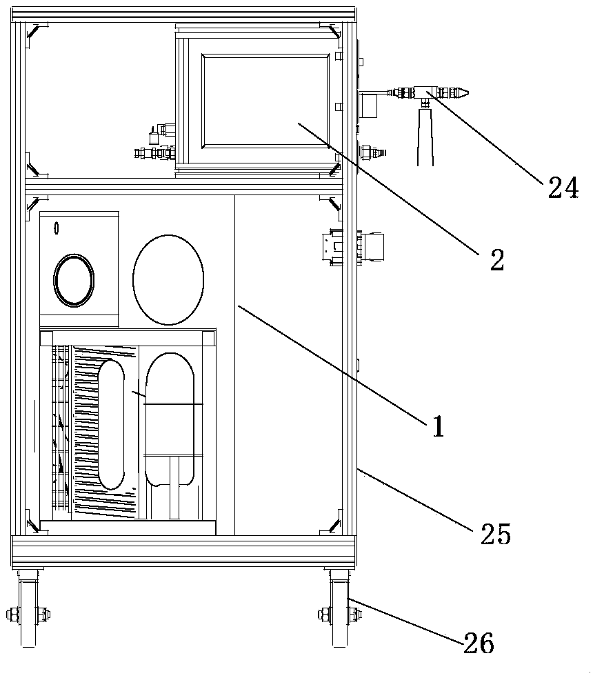
[0023] see figure 1 A schematic structural diagram of an embodiment of the liquid carbon dioxide cleaning system provided by the application, participate in figure 1 The device includes: a liquid carbon dioxide retention system 1 and an injection machine 2, the liquid carbon dioxide retention system 1 and the injection machine 2 are fixedly arranged in the casing shell 25, and universal wheels are also fixedly arranged at the bottom of the casing 26. The setting of the universal wheel 26 can ensure that the liquid carbon dioxide cleaning system can be moved conveniently to meet the needs of production.

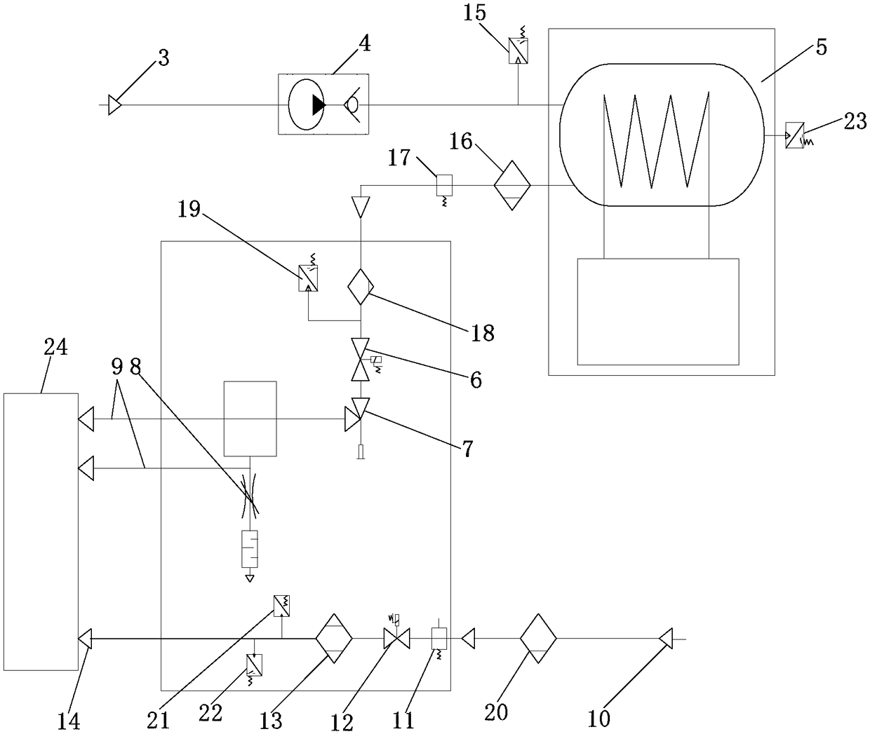
[0024] Such as figure 2 As shown, the liquid carbon dioxide holding system 1 includes a carbon dioxide inlet 3 , a supercharger 4 and a refrigerator 5 . The carbon dioxide inlet port 3 is connected to a carbon dioxide gas source, and the carbon dioxide generating devic...


PUM


Abstract

The embodiment of the invention discloses a liquid carbon dioxide cleaning system which comprises a liquid carbon dioxide keeping system and an injection machine. The carbon dioxide gas inlet end in the liquid carbon dioxide keeping system is connected with the gas inlet end of a refrigerator through a supercharger, and the refrigerator comprises a gas storage channel and a refrigerating device. Aheating subsystem in the injection machine is arranged at the bottom end of the injection machine, a carbon dioxide injection subsystem is adjacently arranged on the side, close to the injection machine, of the heating subsystem, a liquid electromagnetic valve in the carbon dioxide injection subsystem is connected with the gas storage channel of the refrigerator, an adjusting valve is connected with the liquid electromagnetic valve and a first channel of a carbon dioxide outlet, and a throttling valve is connected with a second channel of the carbon dioxide outlet and connected with a hot gasoutlet of the heating subsystem through a spray gun. Supercharged carbon dioxide is cooled through the refrigerator, it is ensured that output liquid carbon dioxide is at low temperature and is keptin a pure liquid state when conveyed by the injection machine, and the cleaning effect is improved.

Description

technical field [0001] The present application relates to the technical field of carbon dioxide cleaning, in particular to a liquid carbon dioxide cleaning system. Background technique [0002] With the advancement of equipment manufacturing technology, the precision of equipment parts has been continuously improved, and the size of parts has been continuously reduced. Therefore, the requirements for the cleanliness of equipment parts are getting higher and higher. Because the attachments on the surface of the parts will affect the stability of the structure and function of the precision equipment, the precision equipment needs to be cleaned repeatedly during the manufacturing process. The cleaning is to effectively remove all kinds of pollution under the premise of not destroying the structure and function of precision equipment parts. Due to the particularity of precision equipment, traditional water cleaning or wiping cleaning cannot meet the needs of cleaning. [0003...

Claims


Application Information

Patent Timeline
IPC IPC(8): B08B7/00
CPCB08B7/0021
Inventor 王杰路远黄一兵
Owner 迪普干冰制造(大连)有限公司
Why Eureka
Try Eureka