Hammering device convenient to move and used for hardware machining

A hammer and hardware technology, which is applied in the field of hardware tool machinery applications, can solve the problems of complicated and troublesome device design, inconvenient operation of the principle, inconvenient installation and disassembly, etc.

Inactive Publication Date: 2018-06-22
昆山万马五金有限公司
View PDF7 Cites 0 Cited by
  • Summary
  • Abstract
  • Description
  • Claims
  • Application Information

AI Technical Summary

Problems solved by technology

[0004] The purpose of the present invention is to solve the problem that although the hardware parts can be easily hammered, it is not easy to move, and the degree of hammering caused by the force of the hammer and the number of times of the hammer cannot be controlled, and the installation and disassembly are relatively inconvenient, and the design of the device is mostly complicated and cumbersome, the principle is inconvenient to operate, and the problem of small energy consumption and large output cannot be achieved, so a mobile hammer device for metal processing is provided.

Method used


Image

  • Hammering device convenient to move and used for hardware machining
  • Hammering device convenient to move and used for hardware machining
  • Hammering device convenient to move and used for hardware machining

Examples


Embodiment 1

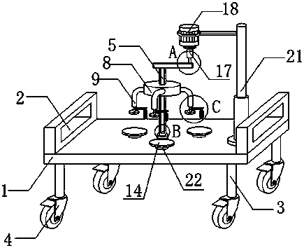
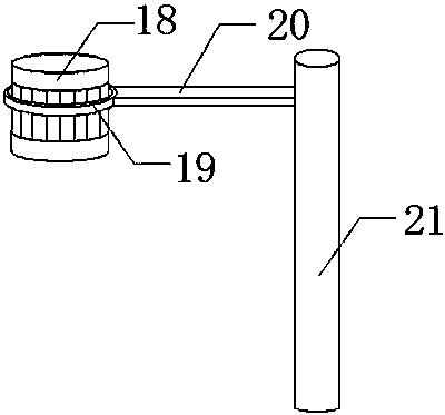
[0024] see Figure 1-5 As shown, a hammer device for metal processing that is easy to move, includes a worktable 1, a universal wheel 4, a chute 6, a connecting rod 9, a baffle 11, a cross column 15, a motor 18, a shaft arm 20 and On the turntable 22, push handles 2 are provided at the edges of both sides of the workbench 1, legs 3 are provided at the four corners of the bottom end of the workbench 1, and universal wheels 4 are provided below the legs 3. The universal wheel 4 is arranged below the universal wheel. Since the universal wheel 4 has good mobility, the device is also movable, which is convenient for the operator to move it, and is convenient for different hardware parts. Hammer operation, and the center of the workbench 1 is provided with a main shaft 5, a number of base plates 14 are arranged around the main shaft 5, and the bottom end of the base plate 14 is provided with a turntable 22, by setting the turntable 22 below the base plate 14, thus in When hammering...

Embodiment 2

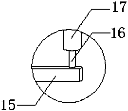
[0026] please continue Figure 1-5 As shown, the difference from the above-mentioned embodiment is: the bottom end of the shaft column 10 is provided with a baffle plate 11, and one side wall of the shaft column 10 is connected with a push plate 12, and one end of the push plate 12 is connected with a hammer block 13, By arranging several hammer blocks 13, the hammering operation can be performed on a corresponding number of hardware parts at the same time. The hammer block 13 and the bottom plate 14 are arranged symmetrically, and the position of the hammer on the hardware parts can be made more accurate by the symmetrical arrangement. The main shaft 5 is embedded with a chute 6, and the top of the main shaft 5 is connected with a horizontal column 15, and the other end of the horizontal column 15 is connected with a vertical column 16, and the top of the vertical column 16 is connected with a rotating shaft 17. By setting the rotating shaft 17, Therefore, the hammer block 1...


PUM


Abstract

The invention discloses a hammering device convenient to move and used for hardware machining. The hammering device comprises a workbench, push handles, supporting legs, universal wheels, a spindle, aslide groove, a round table, an installation disc, connection rods, shaft columns, baffles, push plates, hammer blocks, bottom plates, a transverse column, a vertical column, a rotary shaft, a motor,a clamping ring, a shaft arm, a telescopic column and a rotary disc. The hammering device has the beneficial effects that the universal wheels are arranged under the workbench, due to the fact that the universal wheels have good mobility, the hammering device also has the mobility, an operator can move the hammering device conveniently, and the hammering device can be conveniently used for conducting hammering operation on different hardware parts. By arranging the motor, on one hand, the motor can drive the installation disc to rotate and namely drive the hammer blocks to rotate, so that hammering operation is regularly conducted on the hardware parts; and on the other hand, a power source is provided for all the parts on the hammering device in the moving process.

Description

technical field [0001] The invention relates to a hammer device, in particular to a hammer device for metal processing which is easy to move, and belongs to the field of hardware tool machinery application. Background technique [0002] The hammer device used for hardware processing is a kind of hammer device that needs to be operated to make the hardware parts into the required shape when processing hardware parts. However, the traditional operation is to manually adjust the hardware. For hammering parts, manual operation is not only time-consuming and labor-intensive, but also cannot meet the high-precision requirements of hardware parts. Therefore, a fully automatic mechanical hammering device is required for metal processing. The hammer device is one of them. [0003] However, the existing hammer device for hardware processing still has certain defects in use. Although the existing hammer device for hardware processing can simply hammer the hardware parts, it is not eas...

Claims


Application Information

Patent Timeline
Patent Type & Authority Applications(China)
IPC IPC(8): B25F1/00
CPCB25F1/006
Inventor 马佳佳
Owner 昆山万马五金有限公司
Why Eureka
Try Eureka