

Chinese education ink-grinding device
An ink and language technology, applied in ink tables, printing, office supplies, etc., can solve the problems of wasting time, time and effort, and wasting classroom time.
- Summary
- Abstract
- Description
- Claims
- Application Information
AI Technical Summary
Problems solved by technology
Method used
Image

Examples
Embodiment 1
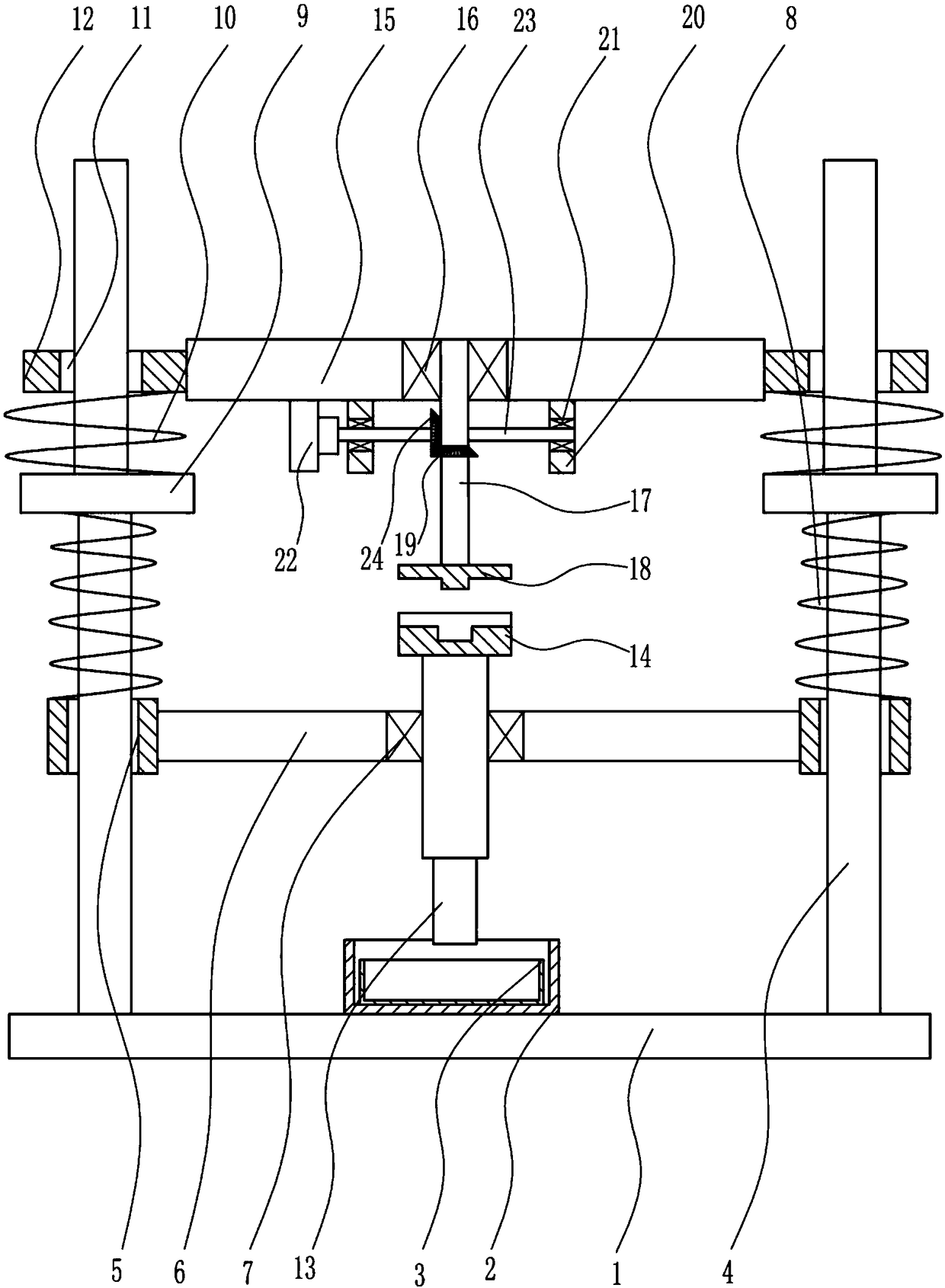
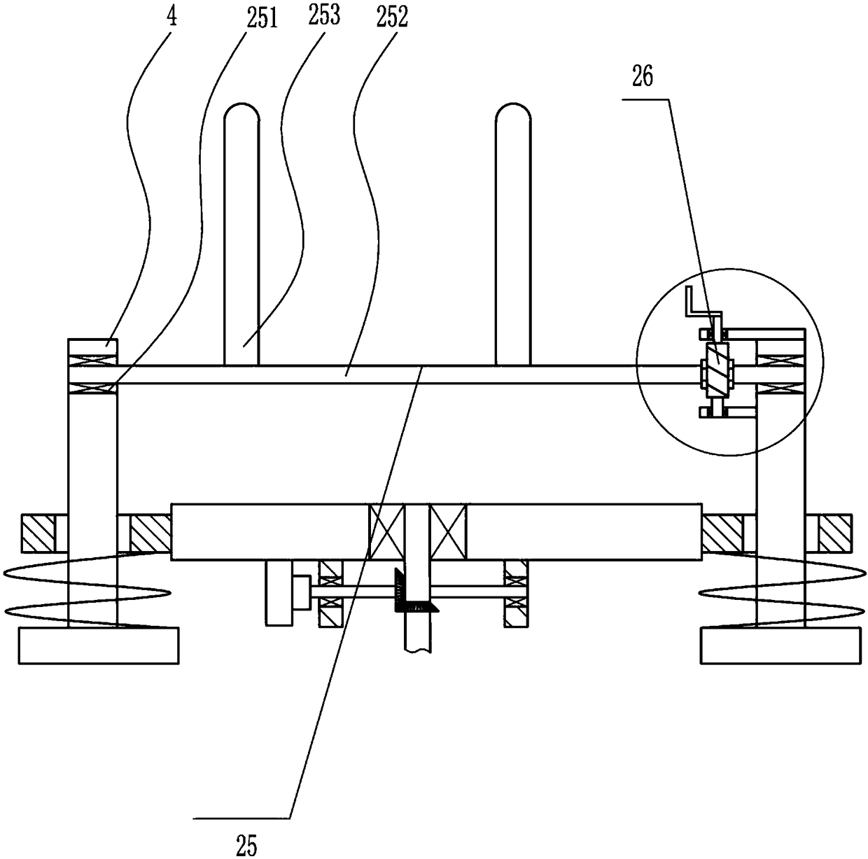
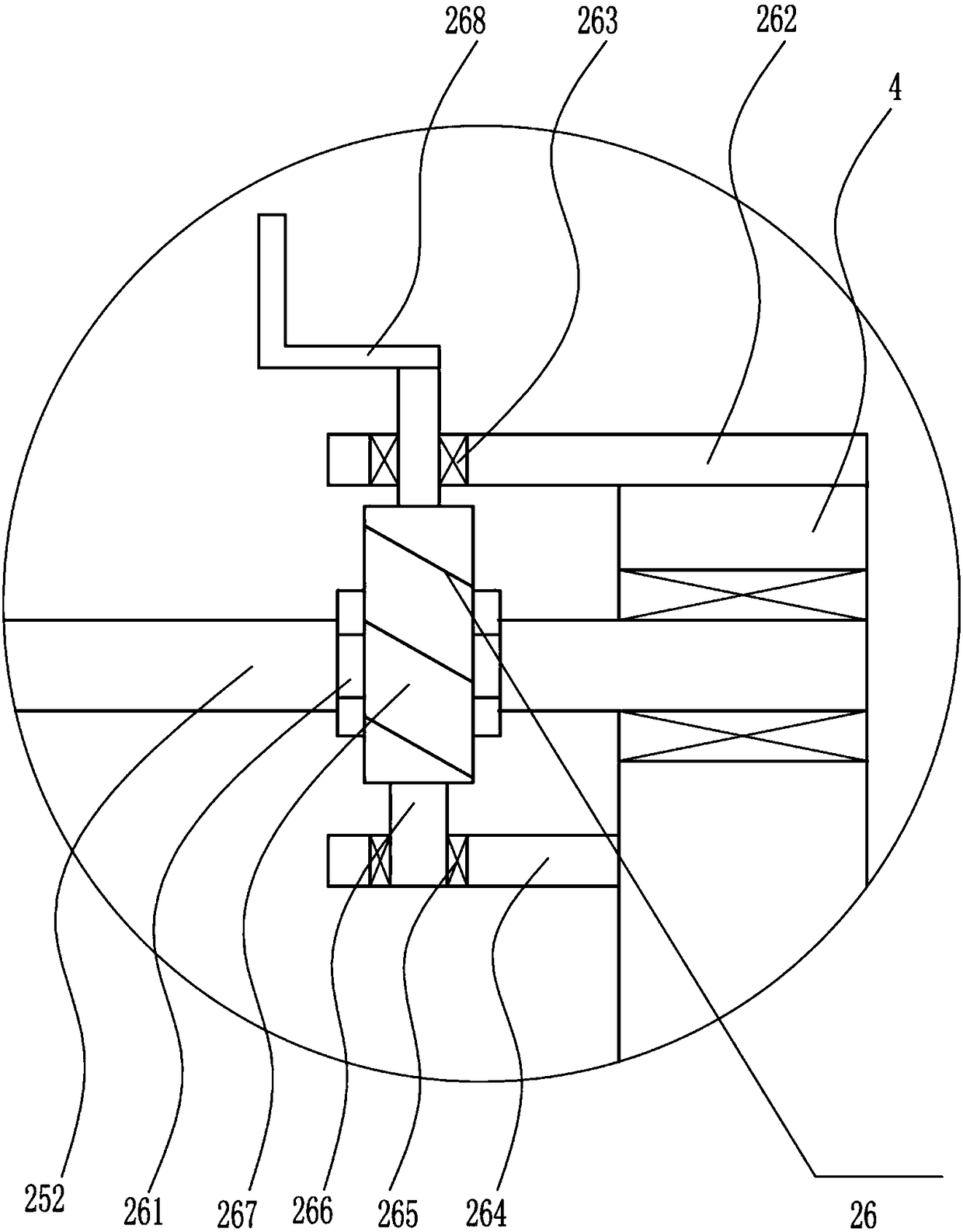
[0030] A Chinese education grinding ink device, such as Figure 1-6As shown, it includes base plate 1, fixed box 2, ink cartridge 3, first bracket 4, first sliding sleeve 5, first connecting rod 6, first bearing 7, first spring 8, first baffle plate 9, the first Two springs 10, the second connecting rod 12, the first rotating shaft 13, the chuck 14, the connecting plate 15, the second bearing 16, the second rotating shaft 17, the bayonet 18, the first bevel gear 19, the first fixed block 20, the second Three bearings 21, a motor 22, a third rotating shaft 23 and a second bevel gear 24 are fixedly connected to the fixed box 2 in the middle of the top of the bottom plate 1, and the inside of the fixed box 2 is provided with an ink cartridge 3, which is symmetrically fixed and connected on the top of the bottom plate 1. The first bracket 4 is connected to the first sliding sleeve 5 in sliding type on the two first brackets 4, and one end of the first connecting rod 6 is fixedly c...
Embodiment 2
[0032] A Chinese education grinding ink device, such as Figure 1-6 As shown, it includes base plate 1, fixed box 2, ink cartridge 3, first bracket 4, first sliding sleeve 5, first connecting rod 6, first bearing 7, first spring 8, first baffle plate 9, the first Two springs 10, the second connecting rod 12, the first rotating shaft 13, the chuck 14, the connecting plate 15, the second bearing 16, the second rotating shaft 17, the bayonet 18, the first bevel gear 19, the first fixed block 20, the second Three bearings 21, a motor 22, a third rotating shaft 23 and a second bevel gear 24 are fixedly connected to the fixed box 2 in the middle of the top of the bottom plate 1, and the inside of the fixed box 2 is provided with an ink cartridge 3, which is symmetrically fixed and connected on the top of the bottom plate 1. The first bracket 4 is connected to the first sliding sleeve 5 in sliding type on the two first brackets 4, and one end of the first connecting rod 6 is fixedly ...
Embodiment 3
[0035] A Chinese education grinding ink device, such as Figure 1-6 As shown, it includes base plate 1, fixed box 2, ink cartridge 3, first bracket 4, first sliding sleeve 5, first connecting rod 6, first bearing 7, first spring 8, first baffle plate 9, the first Two springs 10, the second connecting rod 12, the first rotating shaft 13, the chuck 14, the connecting plate 15, the second bearing 16, the second rotating shaft 17, the bayonet 18, the first bevel gear 19, the first fixed block 20, the second Three bearings 21, a motor 22, a third rotating shaft 23 and a second bevel gear 24 are fixedly connected to the fixed box 2 in the middle of the top of the bottom plate 1, and the inside of the fixed box 2 is provided with an ink cartridge 3, which is symmetrically fixed and connected on the top of the bottom plate 1. The first bracket 4 is connected to the first sliding sleeve 5 in sliding type on the two first brackets 4, and one end of the first connecting rod 6 is fixedly ...
PUM
 Abstract
Description
Claims
Application Information