
Centrifugal compressor circumferential large interval small opening blowing combined with pulse excitation casing

A centrifugal compressor, excitation casing technology, applied in the direction of machine/engine, mechanical equipment, liquid fuel engine, etc., can solve the problems of surge, disadvantage, stable working range stall and surge, etc., achieve low efficiency and simple structure , the effect of convenient application implementation

Active Publication Date: 2019-10-11
NANJING UNIV OF AERONAUTICS & ASTRONAUTICS
View PDF4 Cites 0 Cited by
  • Summary
  • Abstract
  • Description
  • Claims
  • Application Information

AI Technical Summary

Problems solved by technology

Compared with the multi-stage axial flow compressor, the centrifugal compressor has the advantages of simple structure, light weight, small volume, etc., and can maintain high efficiency in a wide operating range, so it is used in car and ship turbochargers, It is widely used in some industrial compressors and aviation compressors, but its stable working range is limited by stall and surge
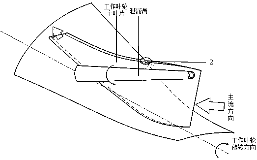
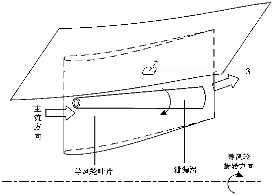
In the flow inside the centrifugal compressor, due to the small flow space, the fluid bears a strong reverse pressure gradient and has a complex vortex structure; the leakage flow structure located at the tip of the rotor is the main cause of flow loss and blockage inside the centrifugal compressor The source has a vital impact on the performance of the compressor's pressure ratio, efficiency, and margin. In severe cases, it will cause the stall and surge of the compressor, which will bring disastrous consequences; after decades of research, many scientific research works Researchers have already had a deep understanding of the compressor rotor blade tip flow, but due to the limitation of its space and the complexity of the flow, it has not been able to realize the effective flow in the compressor according to the existing research results. Control; especially make full use of the internal flow mechanism of the compressor, through some kind of self-circulation adjustment mechanism, at the same time use and improve the flow structure that is not conducive to its performance, so as to achieve the purpose of expanding the stability margin of the centrifugal compressor and expanding the working range of the engine

Method used


Image

  • Centrifugal compressor circumferential large interval small opening blowing combined with pulse excitation casing
  • Centrifugal compressor circumferential large interval small opening blowing combined with pulse excitation casing
  • Centrifugal compressor circumferential large interval small opening blowing combined with pulse excitation casing

Examples


Embodiment Construction

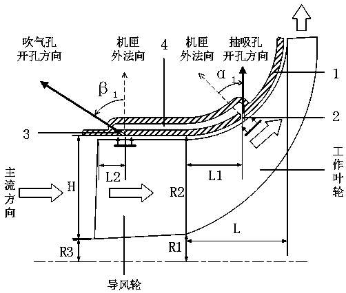
[0019] Centrifugal compressor casing with large intervals and small openings in the circumferential direction combined with blowing and pumping pulse excitation, including centrifugal compressor casing, suction hole structure, blowing hole structure and annular cavity; wherein, the suction hole structure is set in the centrifugal compressor The inner wall of the box is close to the front edge of the working impeller, and the air blowing hole structure is located at the inner wall of the centrifugal compressor casing near the front edge of the wind guide wheel. The suction hole structure and the air blowing hole structure pass through the casing along the cross-sectional area Constant or tapering annular cavity connection; the blowing hole structure has a larger interval along the circumferential direction, and the blowing hole structure has a larger interval along the circumferential direction; the centrifugal compressor has a large circumferential interval and a small opening ...


PUM


Abstract

The invention relates to a circumferential large-interval small-pore blowing and sucking combined pulsed excitation casing of a centrifugal compressor. The circumferential large-interval small-pore blowing and sucking combined pulsed excitation casing comprises a centrifugal compressor casing, a sucking hole structure, a blowing hole structure and an annular cavity, wherein the sucking hole structure is arranged in the position, close to the front edge of an operating impeller, of the inner wall surface of the centrifugal compressor casing; the blowing hole structure is arranged in the position, close to the front edge of an air guide wheel, of the inner wall surface of the centrifugal compressor casing; the sucking hole structure and the blowing hole structure are connected through the annular cavity with the invariant or tapered cross sectional area in the casing in the airflow direction. Through relative motion of the casing and a rotor and the pressure difference between blowing holes and sucking holes, airflow between the sucking hole structure and the blowing hole structure is driven to flow. The circumferential large-interval small-pore blowing and sucking combined pulsed excitation casing has the advantages that the adverse effect on low-energy flow nearby blade tips of the operating impeller and the air guide wheel of the centrifugal compressor is restrained, and the stable operating margin of the centrifugal compressor is enlarged; the total hole area is one or more orders of magnitude less than a general casing and has little influence on the efficiency of the centrifugal compressor; the structure is simple, and implementation is convenient.

Description

technical field [0001] The invention relates to a blowing-pumping combined pulse excitation casing with large intervals and small openings in the circumferential direction of a centrifugal compressor, which belongs to the technical field of impeller machinery. Background technique [0002] The impeller compressor is divided into two basic types: axial flow compressor and centrifugal compressor. Compared with the multi-stage axial flow compressor, the centrifugal compressor has the advantages of simple structure, light weight, small volume, etc., and can maintain high efficiency in a wide operating range, so it is used in car and ship turbochargers, It is widely used in some industrial compressors and aviation compressors, but its stable working range is limited by stall and surge. In the flow inside the centrifugal compressor, due to the small flow space, the fluid bears a strong reverse pressure gradient and has a complex vortex structure; the leakage flow structure locate...

Claims


Application Information

Patent Timeline
Patent Type & Authority Patents(China)
IPC IPC(8): F04D29/42F04D29/68
Inventor 黄国平杨雨轩王进春洪树立张志远
Owner NANJING UNIV OF AERONAUTICS & ASTRONAUTICS
Learn More