Centrifugal compressor casing with large circumferential spacing and small through holes
A technology of centrifugal compressors and large intervals, which is applied in the direction of machines/engines, mechanical equipment, liquid fuel engines, etc., and can solve problems such as increased engine weight and cost, complex pipeline structure and control valves, and reduced compressor efficiency. The effect of convenient application and implementation and simple structure
- Summary
- Abstract
- Description
- Claims
- Application Information
AI Technical Summary
Problems solved by technology
Method used
Image
Examples
Embodiment 1
[0026] Embodiment 1 (taking the centrifugal compressor of a micro-turbojet engine as an example)
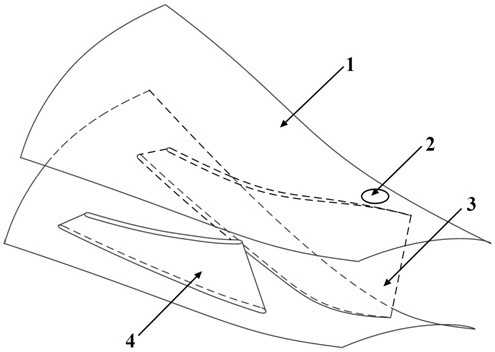
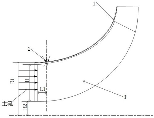
[0027] The casing of the centrifugal compressor has large intervals and small through holes in the circumferential direction, and its structure includes casing 1, through holes 2, main blades 3, and splitter blades 4; through holes 2 are set on the surface of casing 1, main blades 3 and splitter blades 4 Set inside the casing 1.
[0028] There are N1 through-holes 2, which are set around the casing 1 surface at the short distance L1 between the inlet of the rotor impeller and the leading edge of the blade. The number of through-holes 2 is selected with reference to the number of main blades of the centrifugal compressor, and the number of main blades of the compressor is Z, it is known that Z=10, N1 / Z is 0.5, and N1=5.
[0029] The gauge pressure of the internal flow field of the compressor at the position of the through hole is negative, the excitation method is periodic air in...
Embodiment 2
[0032]Embodiment 2 (taking the centrifugal compressor of a micro-turbojet engine as an example)
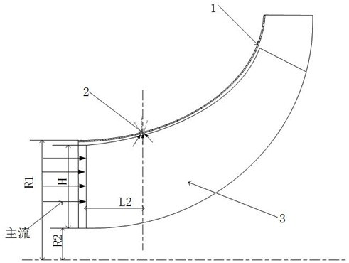
[0033] The casing of the centrifugal compressor has large intervals and small through holes in the circumferential direction, and its structure includes casing 1, through holes 2, main blades 3, and splitter blades 4; through holes 2 are set on the surface of casing 1, main blades 3 and splitter blades 4 Set inside the casing 1.
[0034] There are N1 through-holes 2, which are set around the surface of casing 1 at the long distance L2 between the inlet of the rotor impeller and the leading edge of the blade. The number of through-holes 2 is selected with reference to the number of main blades of the centrifugal compressor, and the number of main blades of the compressor is Z, known Z=10, N1 / Z is 0.5, then N1=5.
[0035] The gauge pressure of the internal flow field of the compressor at the position of the through hole is positive, the excitation method is periodic suction, the di...
PUM
 Abstract
Description
Claims
Application Information
 - R&D
- Intellectual Property
- Life Sciences
- Materials
- Tech Scout
- Unparalleled Data Quality
- Higher Quality Content
- 60% Fewer Hallucinations
Browse by: Latest US Patents, China's latest patents, Technical Efficacy Thesaurus, Application Domain, Technology Topic, Popular Technical Reports.
© 2025 PatSnap. All rights reserved.Legal|Privacy policy|Modern Slavery Act Transparency Statement|Sitemap|About US| Contact US: help@patsnap.com


