
New Centrifugal Compressor with Annular Protrusion Structure

A centrifugal compressor and annular protrusion technology, which is applied in the direction of mechanical equipment, machines/engines, liquid fuel engines, etc., can solve the problems of reducing the working efficiency of centrifugal compressors, deteriorating working performance, and increasing losses, so as to improve stable work Margin, simple structure, effect of preventing backflow phenomenon

Active Publication Date: 2020-06-12
SHANGHAI JIAOTONG UNIV
View PDF5 Cites 0 Cited by
  • Summary
  • Abstract
  • Description
  • Claims
  • Application Information

AI Technical Summary

Problems solved by technology

Because of the existence of reverse flow and vortex, the loss in the compressor will increase, the working efficiency of the centrifugal compressor will be reduced, and the working performance will be deteriorated.

Method used


Image

  • New Centrifugal Compressor with Annular Protrusion Structure
  • New Centrifugal Compressor with Annular Protrusion Structure

Examples

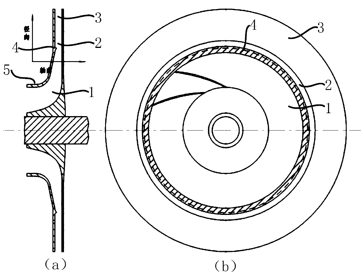

Embodiment Construction

[0024] The present invention will be described in detail below in conjunction with specific embodiments. The following examples will help those skilled in the art to further understand the present invention, but do not limit the present invention in any form. It should be noted that those skilled in the art can make several modifications and improvements without departing from the concept of the present invention. These all belong to the protection scope of the present invention.

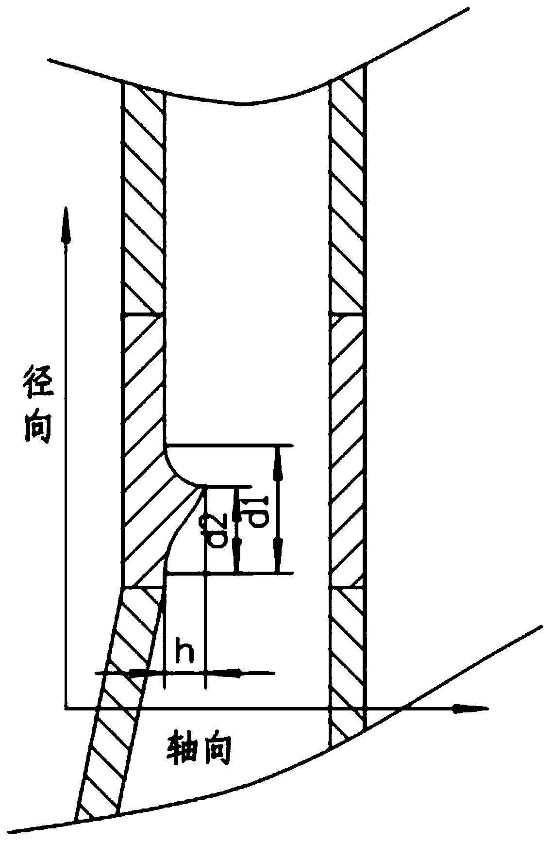
[0025] In this embodiment, the novel centrifugal compressor with an annular protrusion structure provided by the present invention includes a centrifugal compressor body; the centrifugal compressor body includes an impeller wheel cover;

[0026] An annular protrusion structure is provided on the inner side wall of the impeller wheel cover; the annular protrusion structure is connected to the inner side wall of the impeller wheel cover through a circular arc transition;

[0027] The annular protrus...


PUM


Abstract

The invention provides a novel centrifugal compressor with an annular protruding structure. The novel centrifugal compressor comprises a centrifugal compressor body which comprises an impeller cover. The inner side wall of the impeller cover is provided with the annular protruding structure. The annular protruding structure is in arc transition connection with the inner side wall of the impeller cover. The annular protruding structure is arranged in a transition section of the centrifugal compressor body and extends in the peripheral direction of the impeller cover. Any cross sections of the annular protruding structure in the peripheral direction are the same in shape. The novel centrifugal compressor can effectively prevent backflow phenomena close to the wall face, meanwhile can prevent vortex generated in an impeller from flowing to a downstream vaneless diffuser, ensures that airflow can flow smoothly in the transition section, and can work on wider working conditions, and the stable work margin of the compressor is improved.

Description

technical field [0001] The invention relates to a centrifugal compressor, in particular to a novel centrifugal compressor with an annular protrusion structure. Background technique [0002] The centrifugal compressor is an important component, not only used in military aero-engines, but also widely used in civilian fields. To study the flow of gas in the centrifugal compressor, to better control it, and to obtain a high-performance centrifugal compressor is of great significance to the actual research and manufacture of the compressor. [0003] When the gas flows through the compressor, it first passes through the rotating impeller, and the impeller does work on the air flow, increasing the temperature and pressure of the gas. The gas flowing out of the impeller has a high velocity, and what we need is that the airflow has a high pressure energy. In order to achieve this function, there is usually a diffuser before the impeller outlet and the volute, and the airflow deceler...

Claims


Application Information

Patent Timeline
Patent Type & Authority Patents(China)
IPC IPC(8): F04D29/28F04D29/66
CPCF04D29/284F04D29/666
Inventor 杨晓建竺晓程沈昕胡晨星孙翀杜朝辉
Owner SHANGHAI JIAOTONG UNIV
Learn More