Flying insect trap

a technology for flying insects and traps, applied in insect catchers and killers, animal hunting, animal husbandry, etc., can solve the problems of non-toxic attracting liquid, non-optimal concentration, and time-consuming type of systems, and achieve the effects of preventing leakage of attracting materials, reducing assembly steps, and low cos

Active Publication Date: 2006-08-22
SC JOHNSON & SON INC
View PDF29 Cites 33 Cited by
  • Summary
  • Abstract
  • Description
  • Claims
  • Application Information

AI Technical Summary

Benefits of technology

[0011]This structure permits the liquid or other flowable attracting material to be installed in the housing and sealed therein at the factory, prior to shipment to the store. At the same time, the shield stand (the part most susceptible of breakage) can be protected from breakage during shipment by the peel-off cover. Removing the peel-off cover exposes the opening to the attractant and also frees the stand so that it can be pivoted up to hold a shield over the trap. This permits a shield to be mounted in a way that stops rain from directly flowing into the trap, and shades the opening so that it is not lit in a way that helps insects find a way out. Nevertheless, the access by an insect to the attractant is not significantly interfered with. This structure also can use an upper end of the stand for the additional purpose of providing a way to hang the trap.
[0013]However, the trap structure of the present invention can be supplied with an attractant that has been laced with a toxic material if desired, thereby turning the flowable attractant into a baiting material. The device can even be designed to permit some of the insects to escape the trap after being coated with the toxic material, thereby permitting them to return to their nest and contaminate (and thereby control) other insects.
[0021]The present invention thus provides a trap in which the attracting material can be pre-installed at the factory. Leakage of the attracting material is prevented during shipment even though the attracting material is flowable. The trap can quickly be assembled by the homeowner in a manner that is readily conceptually understood. Further, the shield stand is protected during shipment even though it can be made integral with the lid to reduce the assembly steps. Also, the tapered entries inhibit spillage of the liquid bait after the peel-off film is removed, if the trap should accidentally trip over.
[0022]The traps of the present invention can provide their own means of facilitating hanging of the trap, and help protect the attracting material from the elements. This is achieved in an extremely low cost fashion, in part due to the ability to manufacture the components of the trap via automated molding techniques. The final cost of the product can be kept so low that the product can be designed as something that can be disposed of after a defined use period.

Problems solved by technology

Others use materials which are toxic.
However, because the entrance is so small at its junction to the attractant holding cavity the insect typically fails to find the exit, becomes exhausted from trying to do so, and then ultimately drowns in the non-toxic attracting liquid.
This required the homeowner to become involved in mixing the attractant (with the attendant possibility of creating a non-optimal concentration and / or experiencing a spill), and in any event this type of system could be time consuming when multiple traps were to be installed.

Method used


Image

  • Flying insect trap
  • Flying insect trap
  • Flying insect trap

Examples


Embodiment Construction

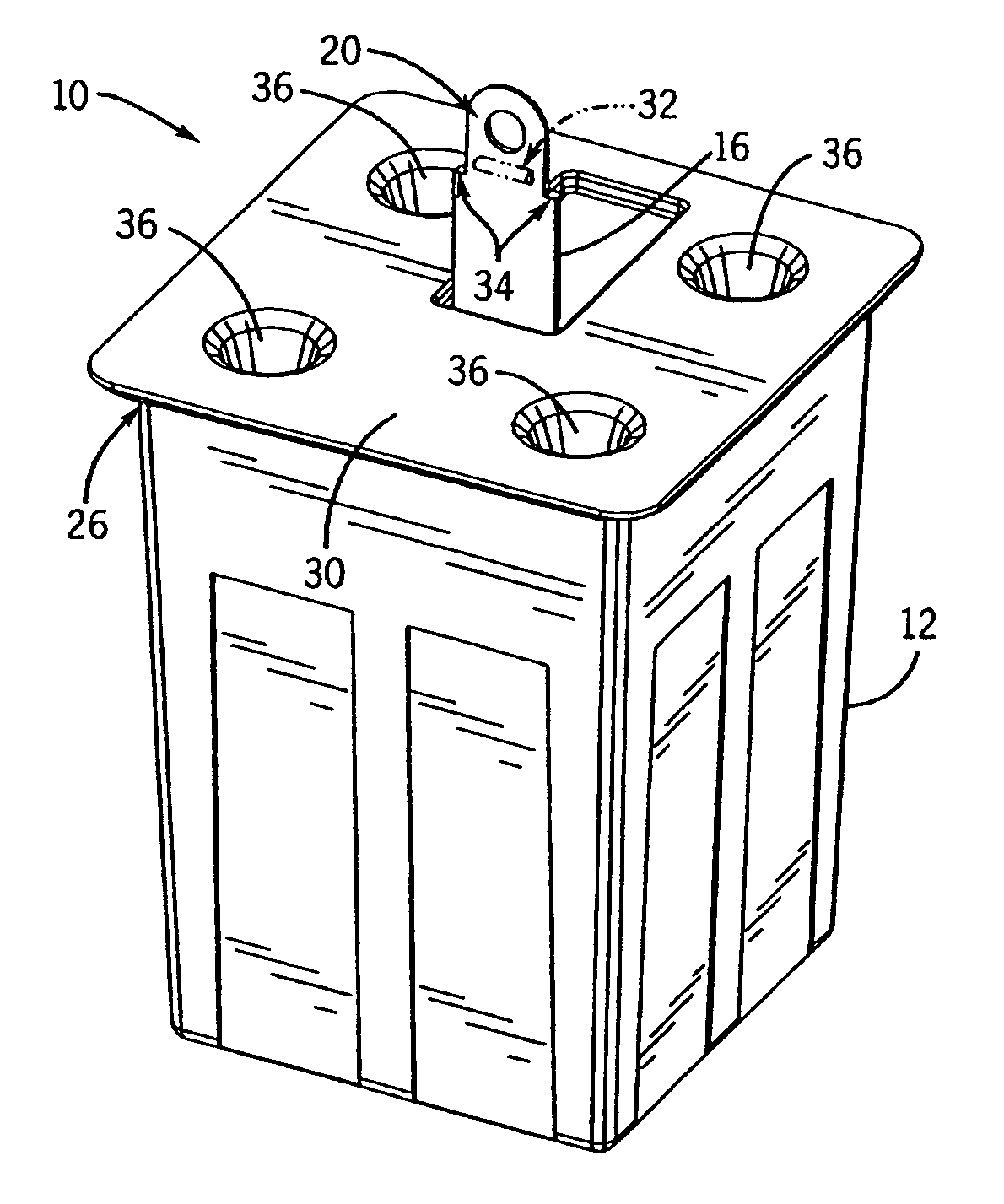
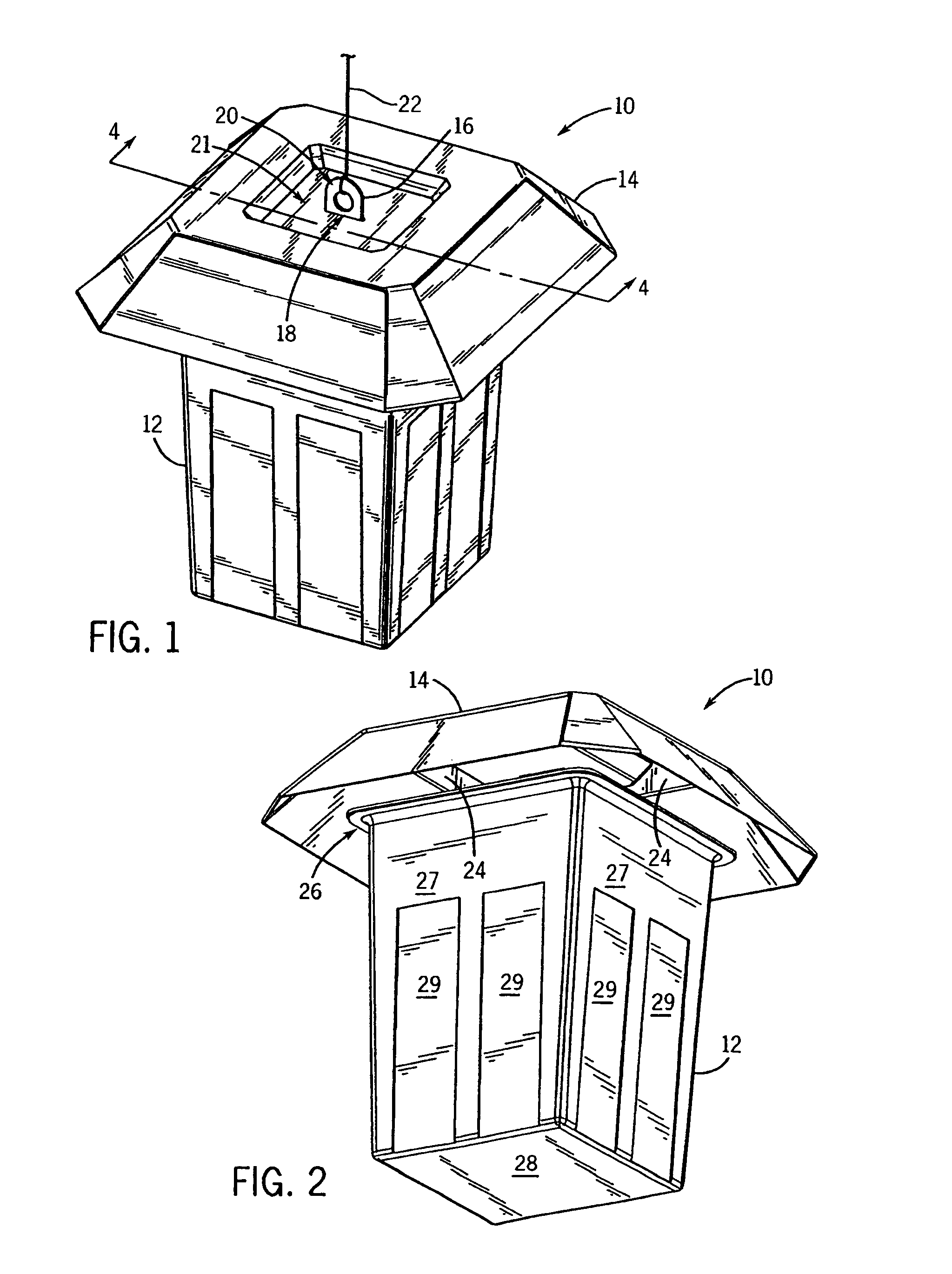
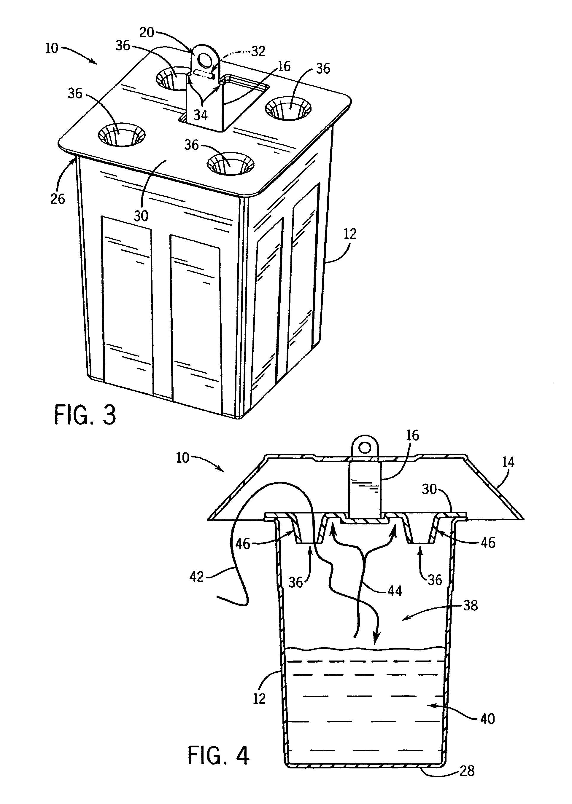
[0031]FIGS. 1–6 depict a first insect trap 10 of the present invention. It is formed from a housing 12 and a shield 14. The shield 14 is mounted via a stand 16 on the housing 12. In the fully assembled form of the trap (FIG. 1) the upper end of the stand 16 extends through a mounting slot 18 in the shield 14 to provide a hole 20 for a hanger 22. The hanger 22 can be a rope, a chain, or a hook. An opposite end of the hanger 22 can be affixed to a support (not shown) such as a gutter, eave, pole or outside light. There can be a depression 21 in the top wall of the shield 14 to facilitate gripping of the upper end of the stand during the hanging process by allowing the stand 16 to project farther above the shield than it otherwise would. If that effect is not needed with respect to particular proportions of a given trap, depression can be eliminated so as to permit the shield 14 to more readily shed rain water and debris.

[0032]With particular reference to FIG. 2, when the shield 14 is ...


PUM


Abstract

Traps are disclosed for controlling flying insects such as wasps. The traps are pre-packaged with attracting liquid prior to sale, and then sealed with a peel-off film in a manner that prevents leakage prior to use. When the trap is about to be used, the peel-off film is removed to expose both a trap entry and a pivotable stand. A rain / sun shield is then mounted on the stand, preferably with the upper portion of the stand projecting through the shield to form part of a hanger.

Description

CROSS-REFERENCE TO RELATED APPLICATIONS[0001]Not applicableSTATEMENT REGARDING FEDERALLY SPONSORED RESEARCH / DEVELOPMENT[0002]Not applicableBACKGROUND OF THE INVENTION[0003]The present invention relates to traps for controlling flying insects. More specifically, it relates to an insect trap which can be pre-loaded with liquid or other flowable attracting material prior to sale, yet provide ready access to the attracting material once the trap is installed for use.[0004]A variety of traps have been devised for trapping flying insects. Some of these traps rely on electricity to power attracting or retaining devices. Others use materials which are toxic. Still others use replaceable sticky sheets. While these approaches do create functional insect traps, it is desired to have insect traps for certain applications which do not require electrical power, toxic materials, or replaceable sticky sheets.[0005]A variety of traps have been developed for controlling wasps, yellow jackets and bees...

Claims


Application Information

Patent Timeline
Patent Type & Authority Patents(United States)
IPC IPC(8): A01M1/20
CPCA01M1/106A01M2200/012
Inventor MEIER, MAUDE CHRISTIANDUSTON, TYLER D.MINEAU, STEVEN B.KEYEL, RICHARD E.HEATHCOCK, JOHN A.
Owner SC JOHNSON & SON INC
Why Eureka
Try Eureka