
Embolic protection systems

a protection system and embolic technology, applied in the field of embolic protection systems, can solve the problems of inability to protect the vessel, stroke, infarction, etc., and achieve the effect of expanding the expandable structure within the patient's vasculatur

Active Publication Date: 2010-03-11
TYCO HEALTHCARE GRP LP
View PDF83 Cites 35 Cited by
  • Summary
  • Abstract
  • Description
  • Claims
  • Application Information

AI Technical Summary

Benefits of technology

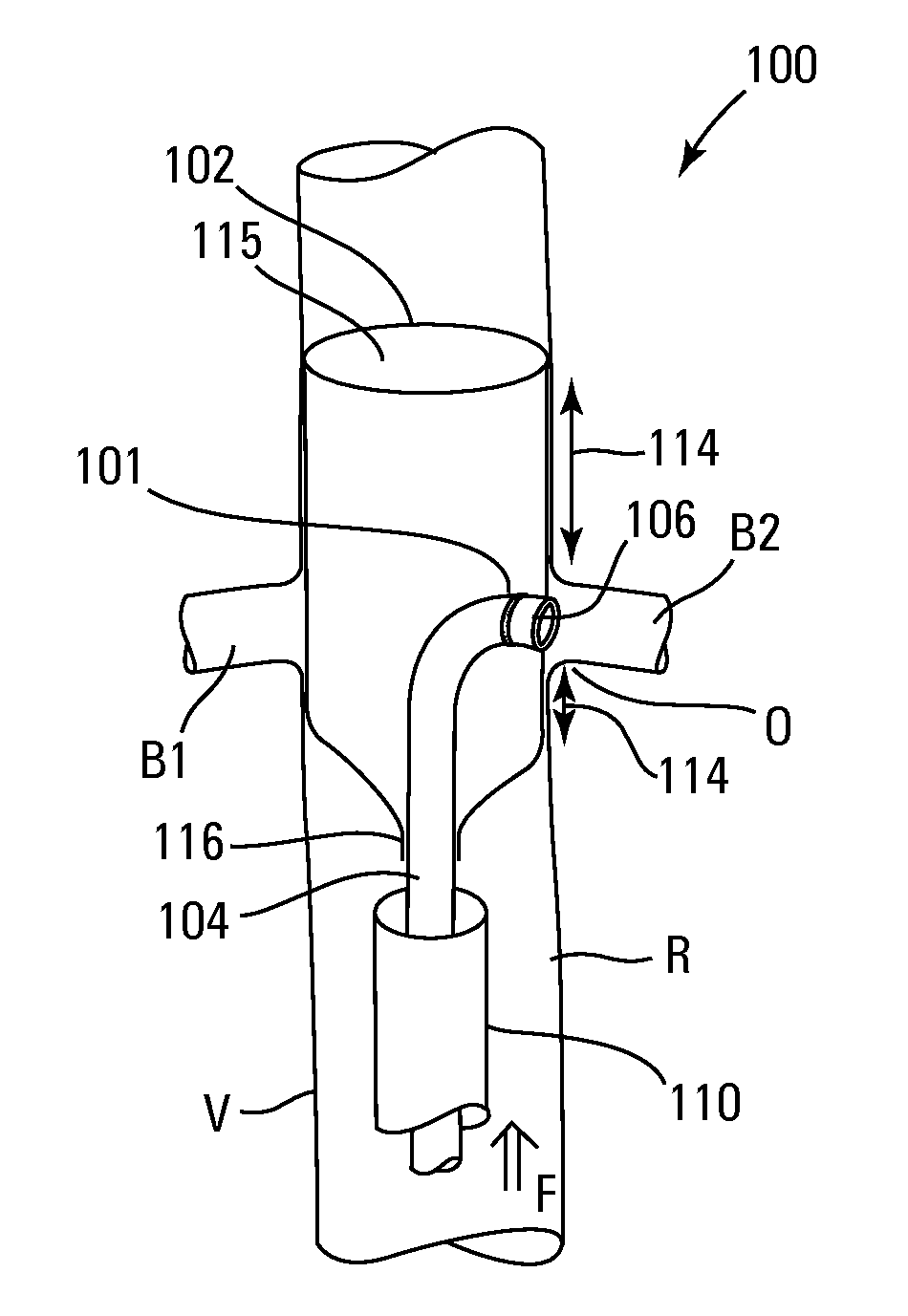
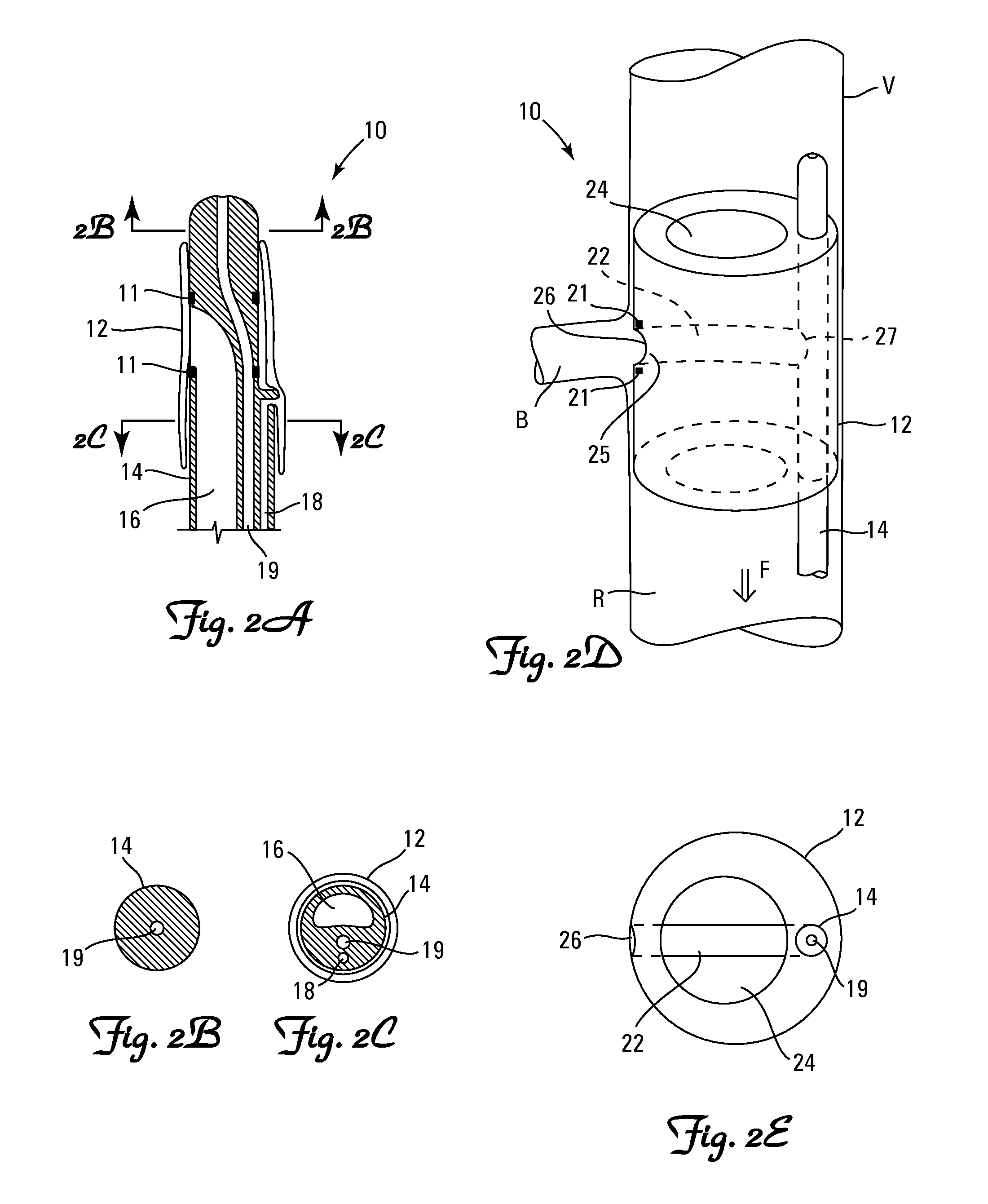
[0009]The invention provides an embolic protection device comprising an expandable structure and a catheter, the catheter having a distal region and having a working channel, the working channel having a working channel opening disposed in the distal region of the catheter, the working channel and the working channel opening dimensioned to slideably receive an interventional device, the working channel having a distal region, at least a portion of the distal region of the working channel being disposed within the expandable structure, the expandable structure, when expanded in a first blood vessel, is able to stop blood flow through a second blood vessel and able to allow blood to flow through the first blood vessel, and the working channel opening is able to be disposed to allow an interventional device to enter the second blood vessel.

Problems solved by technology

Infarcts, strokes, and other major or minor adverse events are caused when debris embolizes into vasculature distal to the treatment site.
However, some anatomies present specific challenges due to the anatomical shape or configuration.
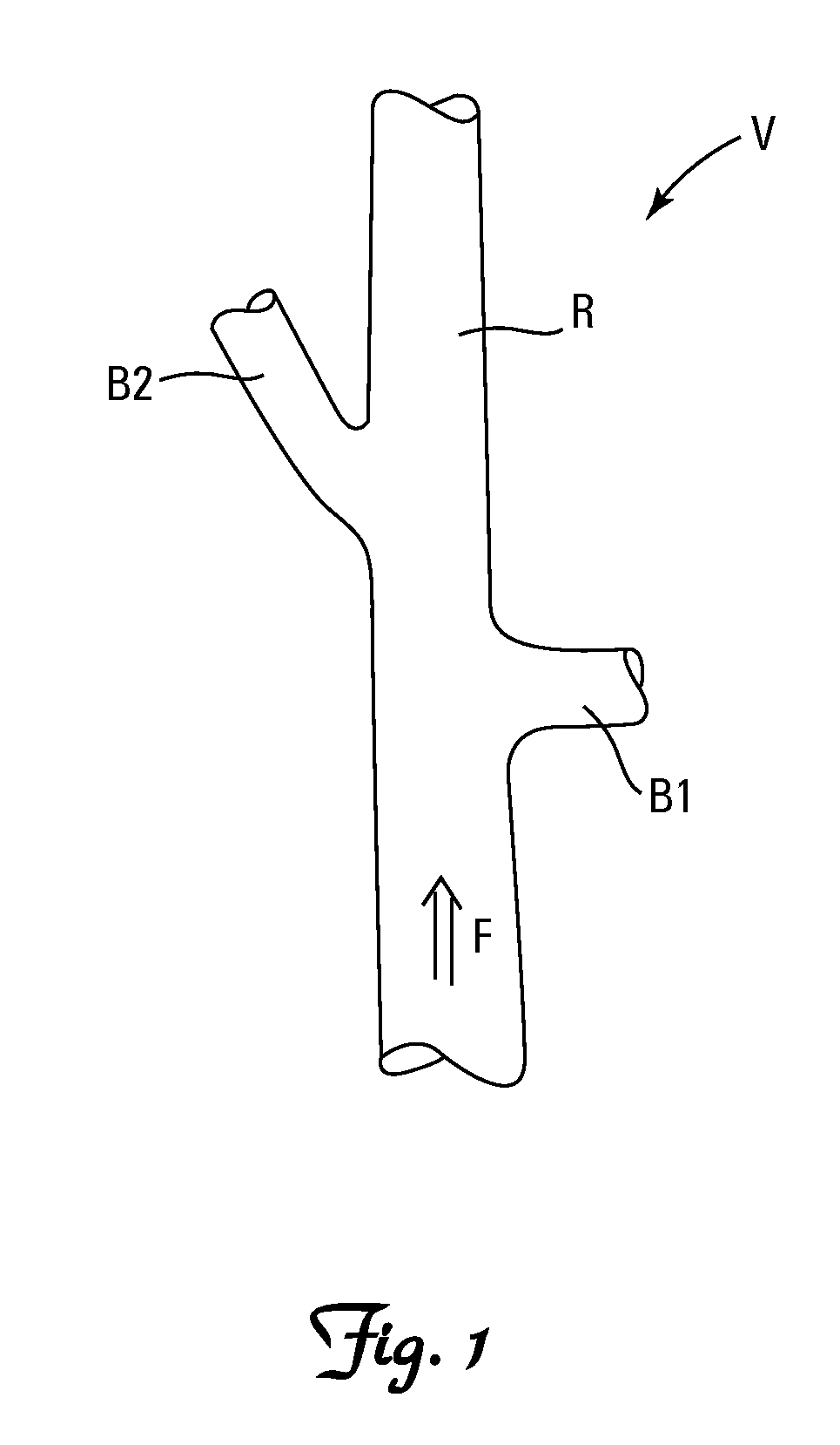
Known embolic protection devices are generally unsuitable for protection of vessels downstream of lesions at or near bifurcations because it is hard to protect both distal branches.
Another challenging situation involves treatment of arteriosclerotic disease in branch vessels, for example at the ostium of renal arteries within the human body.
Known embolic protection devices are generally unsuitable for protection of vessels downstream of lesions at or near the main renal artery because the artery is short and divides downstream into three or more additional branch vessels.

Method used


Image

  • Embolic protection systems
  • Embolic protection systems
  • Embolic protection systems

Examples


Embodiment Construction

[0032]The terms “distal” and “proximal” as used herein refer to the relative position of the guidewire and catheters in a lumen. The most “proximal” point of the catheter is the end of the catheter extending outside the body closest to the physician. The most “distal” point of the catheter is the end of the catheter placed farthest into a body lumen from the entrance site.

[0033]The invention provides an embolic protection device comprising an expandable structure and a catheter, the catheter having a distal region and having a working channel dimensioned to slideably receive an interventional device, the expandable structure being attached to the distal region of the catheter, the expandable structure having an expandable working channel extension and a working channel opening, the expandable working channel extension having a proximal end and a distal end, the proximal end of the working channel extension being attached to a distal end of the working channel, the distal end of the ...


PUM


Abstract

An embolic protection device comprising an expandable structure and a catheter. The catheter has a distal region and a working channel dimensioned to slideably receive an interventional device. The expandable structure is attached to the distal region of the catheter. The expandable structure has an expandable working channel extension and a working channel opening, the expandable working channel extension has a proximal end and a distal end, the proximal end of the working channel extension is attached to a distal end of the working channel, and the distal end of the working channel extension forms the working channel opening. The working channel opening is disposed proximate an exterior surface of the expandable structure when the expandable structure is expanded. The working channel, working channel extension, and the working channel opening form a continuous lumen.

Description

[0001]This application is a continuation of U.S. application Ser. No. 11 / 715,266, filed Mar. 7, 2007, which claims the benefit of U.S. Provisional Application No. 60 / 781,059, filed Mar. 10, 2006, entitled “Embolic Protection Systems”, the contents of each of which are hereby incorporated by reference herein.FIELD OF THE INVENTION[0002]The present invention relates to embolic protection systems. These embolic protection systems are particularly well-suited for use in branched blood vessels.BACKGROUND OF THE INVENTION[0003]Vessels are commonly treated to reduce or eliminate narrowings caused by arteriosclerotic disease. Interventional treatments can include use of balloon angioplasty, stenting, thrombectomy, atherectomy, and other procedures. During treatment particulate debris can be generated at the treatment site. Infarcts, strokes, and other major or minor adverse events are caused when debris embolizes into vasculature distal to the treatment site.[0004]To prevent embolization of...

Claims


Application Information

Patent Timeline
Patent Type & Authority Applications(United States)
IPC IPC(8): A61F2/01A61M29/00
CPCA61F2/013A61F2250/0098A61M25/0032A61M25/1002A61F2002/018A61F2230/0006A61F2230/0067A61F2230/008A61B2017/3484A61F2/958A61F2002/011A61F2002/016A61F2002/9583A61F2210/0014A61F2002/061A61F2/014A61F2/011
Inventor REN, BROOKELININGER, JAMES R.KUSLEIKA, RICHARD S.
Owner TYCO HEALTHCARE GRP LP
Learn More