
A pulse solenoid valve

A technology of pulse solenoid valve and valve body, which is applied in the direction of valve details, valve device, valve shell structure, etc., can solve the problems of reducing the reaction speed, effectively cleaning the internal cavity, affecting the sealing performance of pulse solenoid valve, etc., so as to prevent sealing failure problem, save cleaning time, and facilitate independent cleaning

Active Publication Date: 2019-11-29
NINGBO JLT ELECTRIC CO LTD
View PDF5 Cites 0 Cited by
  • Summary
  • Abstract
  • Description
  • Claims
  • Application Information

AI Technical Summary

Problems solved by technology

[0003] Traditionally, due to the limitation of the structure, it is difficult to effectively clean the internal cavity of the pulse solenoid valve after long-term use, or when cleaning, the pulse solenoid valve needs to be disassembled to perform effective cleaning. After disassembly and assembly for the first time, it may affect the sealing performance of the pulse solenoid valve and reduce its response speed, thereby affecting the performance of the pulse solenoid valve; and it takes time to process the cleaning liquid after cleaning, which wastes a lot of time and easily causes the suspension of the equipment , affecting normal use; and the traditional cleaning method also has the problem of incomplete cleaning

Method used


Image

  • A pulse solenoid valve
  • A pulse solenoid valve

Examples


Embodiment Construction

[0017] In order to make it easy to understand the technical means, creative features, goals and effects achieved by the present invention, the following examples are combined with the appended figure 1 to attach figure 2 The technical solutions provided by the present invention are described in detail, but the following content is not intended as a limitation of the present invention.

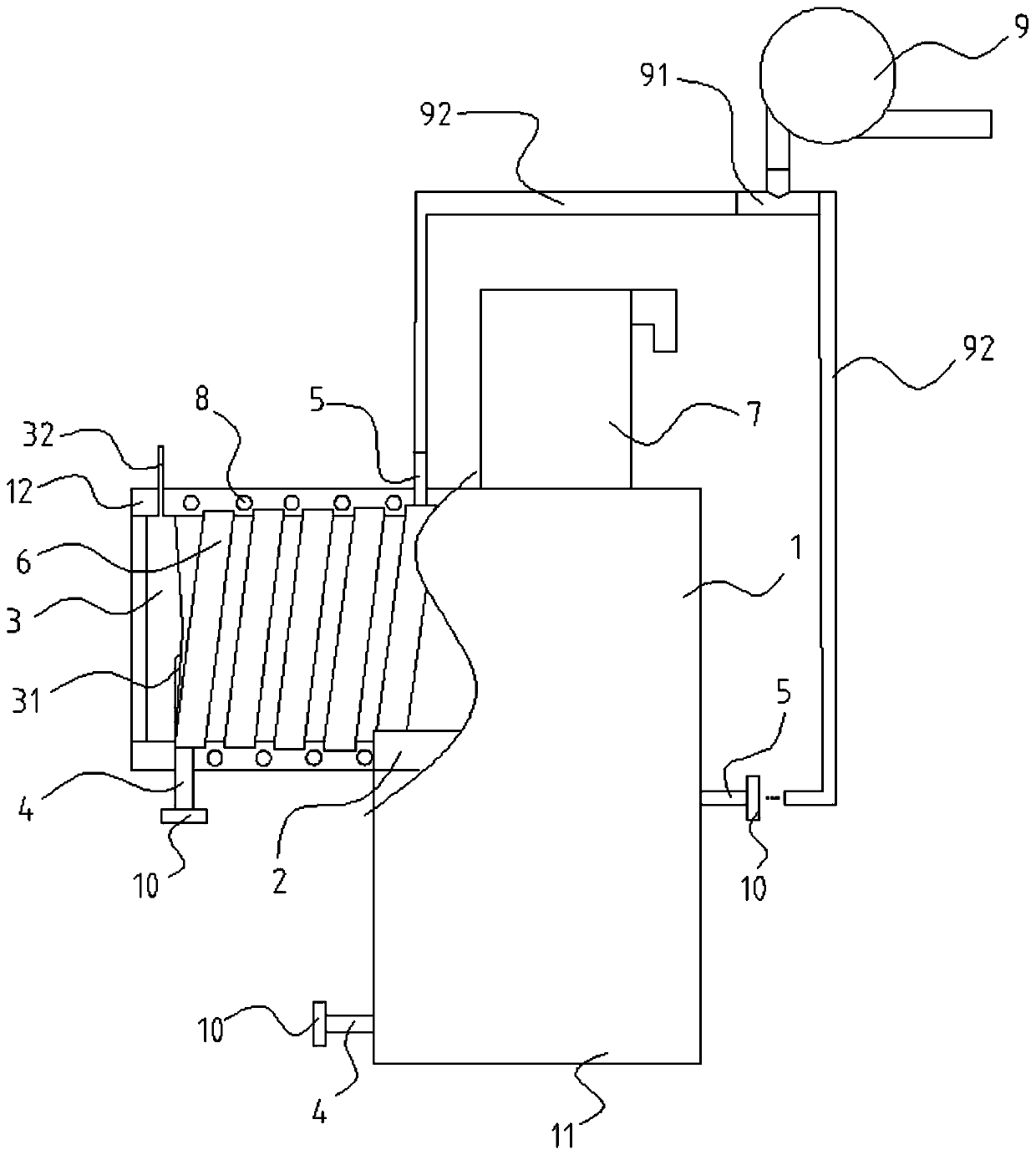
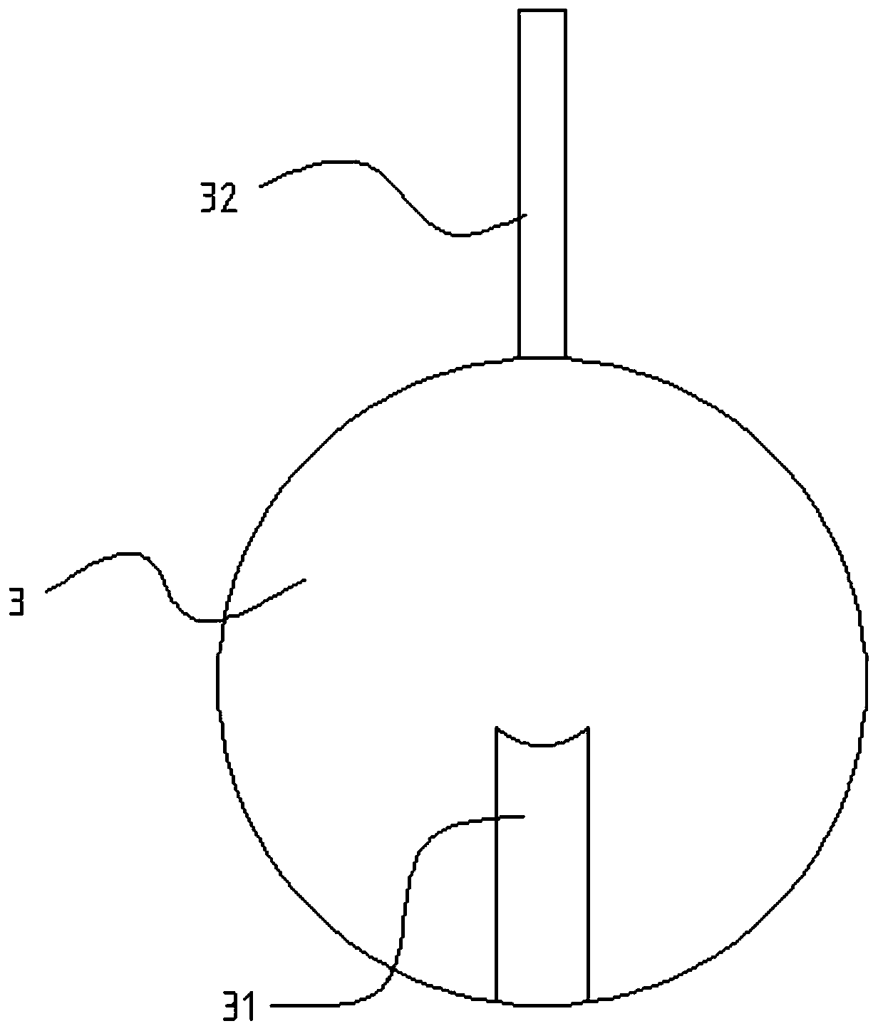
[0018] figure 1 It is a structural diagram of an embodiment of a pulse solenoid valve of the present invention; figure 2 It is a structural diagram of a control valve in a preferred embodiment of the present invention. Such as figure 1 and figure 2 As shown, the pulse solenoid valve provided in this embodiment includes: valve body 1, inlet 11, outlet 12, diaphragm 2, control valve 3, diversion port 31, valve stem 32, sewage outlet 4, liquid inlet hole 5, seal Cover 10 , diversion tank 6 , pulse structure 7 , heating coil 8 , liquid supply electric pump 9 , diverting tee 91 and conduit 9...


PUM


Abstract

The invention provides a pulse solenoid valve, and belongs to the technical field of valves. The pulse solenoid valve comprises normally-opened rotary control valves which are arranged at an inlet andan outlet of a valve body, wherein a sewage draining port and a liquid inlet hole which are provided with sealing covers are formed in the wall body of the valve body; a spiral flow guide groove is formed in the inner wall, between the sewage draining port and the liquid inlet hole, of the valve body. According to the pulse solenoid valve, the control valves are arranged, so that washing liquid can be prevented from flowing to other devices during washing; in addition, the sewage draining port and the liquid inlet hole are formed, so that the valve body can be washed without dismounting, andthe fact that mounting and dismounting of a plurality of times influence the sealing performance of the pulse solenoid valve, resulting in the influence on the use performance of the pulse solenoid valve, can be avoided; and meanwhile, the spiral flow guide groove is formed, so that tangential impact force can be produced by the washing liquid, and as a result, the valve can be flushed and completely cleaned; in addition, a heating coil is arranged and capable of quickly evaporating the washing liquid after washing, so that the washing time is reduced, and the residues of the washing liquid can be avoided.

Description

technical field [0001] The invention relates to the technical field of valves, in particular to a pulse electromagnetic valve. Background technique [0002] Pulse solenoid valves are widely used due to the advantages of low power consumption, short instantaneous power-on time, and wide operating pressure range. [0003] Traditionally, due to the limitation of the structure, it is difficult to effectively clean the internal cavity of the pulse solenoid valve after long-term use, or when cleaning, the pulse solenoid valve needs to be disassembled to perform effective cleaning. After disassembly and assembly for the first time, it may affect the sealing performance of the pulse solenoid valve and reduce its response speed, thereby affecting the performance of the pulse solenoid valve; and it takes time to process the cleaning liquid after cleaning, which wastes a lot of time and easily causes the suspension of the equipment , affecting normal use; and the traditional cleaning ...

Claims


Application Information

Patent Timeline
Patent Type & Authority Patents(China)
IPC IPC(8): F16K43/00F16K27/02
CPCF16K27/0218F16K43/003
Inventor 胡芳丽
Owner NINGBO JLT ELECTRIC CO LTD
Learn More