Gear transmission type mobile phone supporting device

A technology of supporting device and gear transmission, applied in machine/stand, supporting machine, mechanical equipment, etc., can solve the problems of poor user experience, laborious picking and placing of mobile phones, matching charging of wireless charging base, etc., to improve user experience and convenience. The effect of picking and placing mobile phones to facilitate secondary development

Pending Publication Date: 2018-06-22
深圳市智高翔科技发展有限公司
View PDF9 Cites 8 Cited by
  • Summary
  • Abstract
  • Description
  • Claims
  • Application Information

AI Technical Summary

Problems solved by technology

[0002] The mobile phone support device is a device placed on the desktop, the center console of the car, etc., to support and clamp the mobile phone. Most of the existing mobile phone support devices adopt the jaw structure, and rely on the spring between the two jaws to realize the elastic clip. When using it, it is necessary to manually overcome the elastic stress between the jaws to place the mobile phone between the two jaws. Similarly, when removing the mobile phone, it is still necessary to overcome the elastic force between the two jaws, which leads to the difficulty of picking and placing the mobile phone. Laborious, inconvenient to use, poor user experience
In addition, the existing mobile phone supporting device only has a supporting function. For some mobile phones with wireless charging function, when they are placed on the mobile phone supporting device, they cannot be matched with the wireless charging stand for charging, so that when the mobile phone is clamped on the bracket, it cannot be charged. Wireless charging is difficult to meet market demand

Method used


Image

  • Gear transmission type mobile phone supporting device
  • Gear transmission type mobile phone supporting device
  • Gear transmission type mobile phone supporting device

Examples


Embodiment Construction

[0028] The present invention will be described in more detail below in conjunction with the accompanying drawings and embodiments.

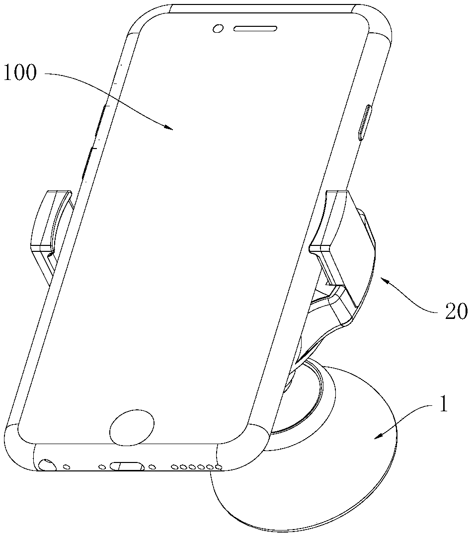
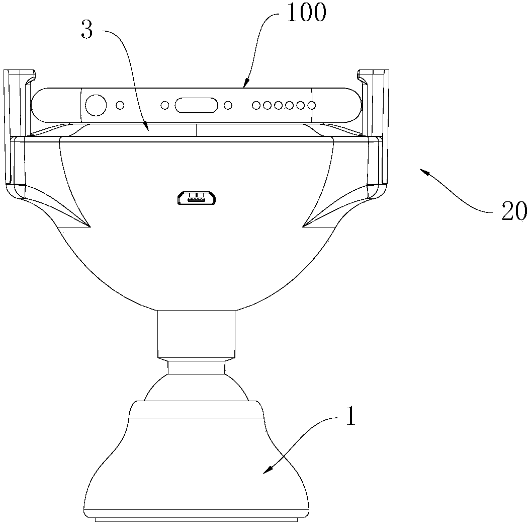
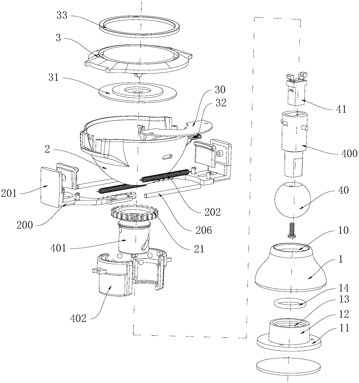
[0029] The invention discloses a gear transmission type mobile phone supporting device, which combines Figure 1 to Figure 12 As shown, it includes a base 1, the base 1 is provided with a driving mechanism, the upper end of the driving mechanism is provided with a housing 2, and the housing 2 is provided with a clamping mechanism, and the clamping mechanism includes Two opposite jaws 20, the jaws 20 are slidably connected with the housing 2, the jaws 20 are "L" shaped jaws comprising a horizontal arm 200 and a vertical arm 201, the two Each horizontal support arm 200 is located in the housing 2, the ends of the two horizontal support arms 200 are oppositely arranged, and a tension spring 202 is connected between the two horizontal support arms 200, and the tension applied by the tension spring 202 Pulling force makes the two jaws 20 close to eac...


PUM


Abstract

The invention discloses a gear transmission type mobile phone supporting device. The gear transmission type mobile phone supporting device comprises a base, a driving mechanism is arranged on the base, a shell is arranged at the upper end of the driving mechanism, a clamping mechanism is arranged on the shell and comprises two clamping jaws which are oppositely arranged, the clamping jaws are connected to the shell in a sliding mode and are L-shaped clamping jaw which comprise horizontal supporting arms and vertical supporting arms, tension springs are connected between the two horizontal supporting arms, a gear is arranged in the shell, straight racks are formed at the end parts of the horizontal support arms, the two straight racks are arranged on the two sides of the gear separately andmesh with the gear, the driving mechanism is used for applying the torsion to the gear, and the gear is stressed to rotate and drives the two horizontal supporting arms to slide outwards so as to enable the two clamping jaws to be far away from each other. The gear transmission type mobile phone supporting device has the advantages that the two clamping jaws can be stressed by the aid of the driving mechanism, so that a mobile phone can be clamped, picked and placed accordingly, and therefore the operation is convenient, and time and labor are saved.

Description

technical field [0001] The invention relates to mobile phone supporting equipment, in particular to a gear transmission type mobile phone supporting device. Background technique [0002] The mobile phone support device is a device placed on the desktop, the center console of the car, etc., and is used to support and clamp the mobile phone. Most of the existing mobile phone support devices adopt the claw structure, and rely on the spring between the two claws to realize the elastic clip. When using it, it is necessary to manually overcome the elastic stress between the jaws to place the mobile phone between the two jaws. Similarly, when taking off the mobile phone, it is still necessary to overcome the elastic force between the two jaws, which leads to the difficulty of picking and placing the mobile phone. Laborious, inconvenient to use, and poor user experience. In addition, the existing mobile phone supporting device only has a supporting function. For some mobile phones ...

Claims


Application Information

Patent Timeline
Patent Type & Authority Applications(China)
IPC IPC(8): F16M11/04H04M1/04
CPCH04M1/04F16M11/04
Inventor 朱长仙
Owner 深圳市智高翔科技发展有限公司
Why Eureka
Try Eureka