A protection verification test wiring structure
A technology of test wiring and test leads, applied in the direction of test/measurement connectors, connections, contact parts, etc., to achieve good connection stability, reasonable structure, and avoid poor contact effects
- Summary
- Abstract
- Description
- Claims
- Application Information
AI Technical Summary
Problems solved by technology
Method used
Image
Examples
Embodiment 1
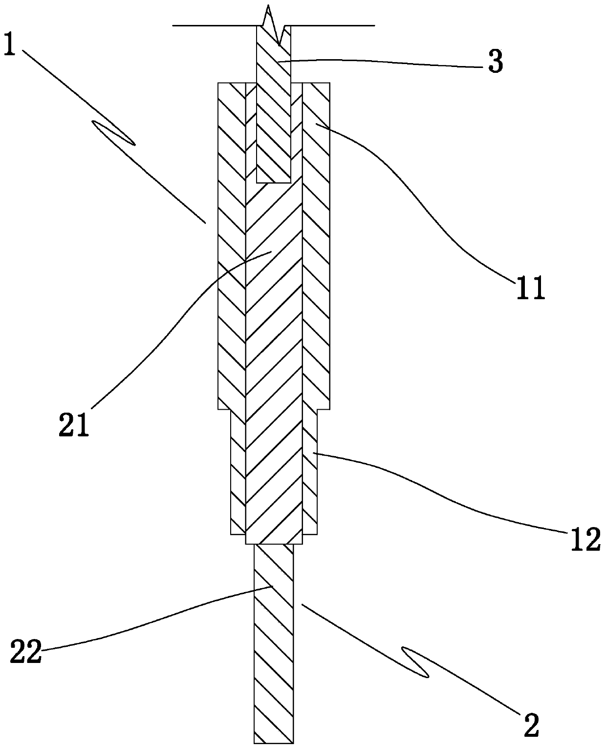
[0022] Embodiment 1: as Figure 1 to Figure 3 In the shown embodiment, a protection verification test wiring structure includes
[0023] An outer insulating sleeve 1, an extended conductive rod 2 and a test lead, the test lead includes a lead body and a plug connector 3;
[0024] The extended conductive rod includes an upper rod section 21 and a lower rod section 22 coaxially connected with the upper rod section. The lower rod section is provided with external threads, the outer insulating sleeve is set outside the upper rod section, and the upper end of the upper rod section is provided with a plug joint. Adapted socket;
[0025] The outer insulating sleeve includes a rotating grip square sleeve 11 and an extending round sleeve 12 arranged at the lower end of the rotating grip square sleeve. The rotating grip square sleeve is connected with the extending round sleeve. high.
[0026] In the axial direction of the extension sleeve: the projection of the extension sleeve fall...
Embodiment 2
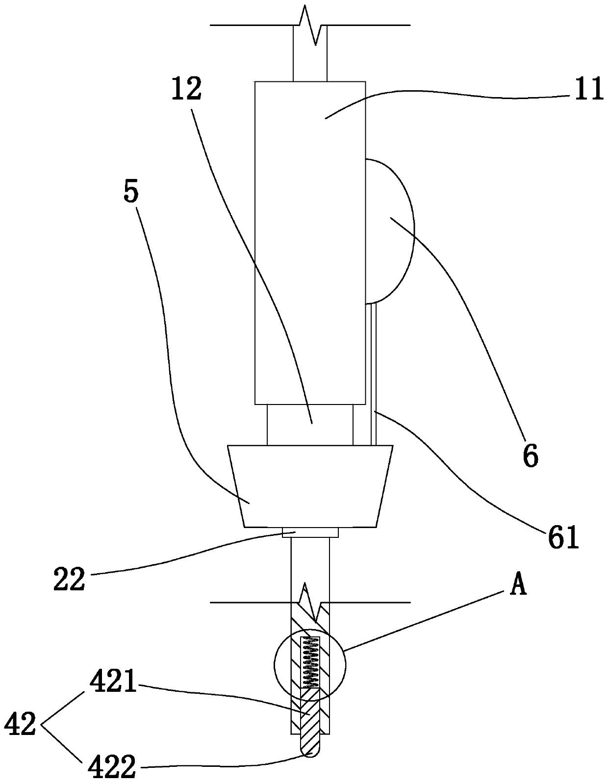
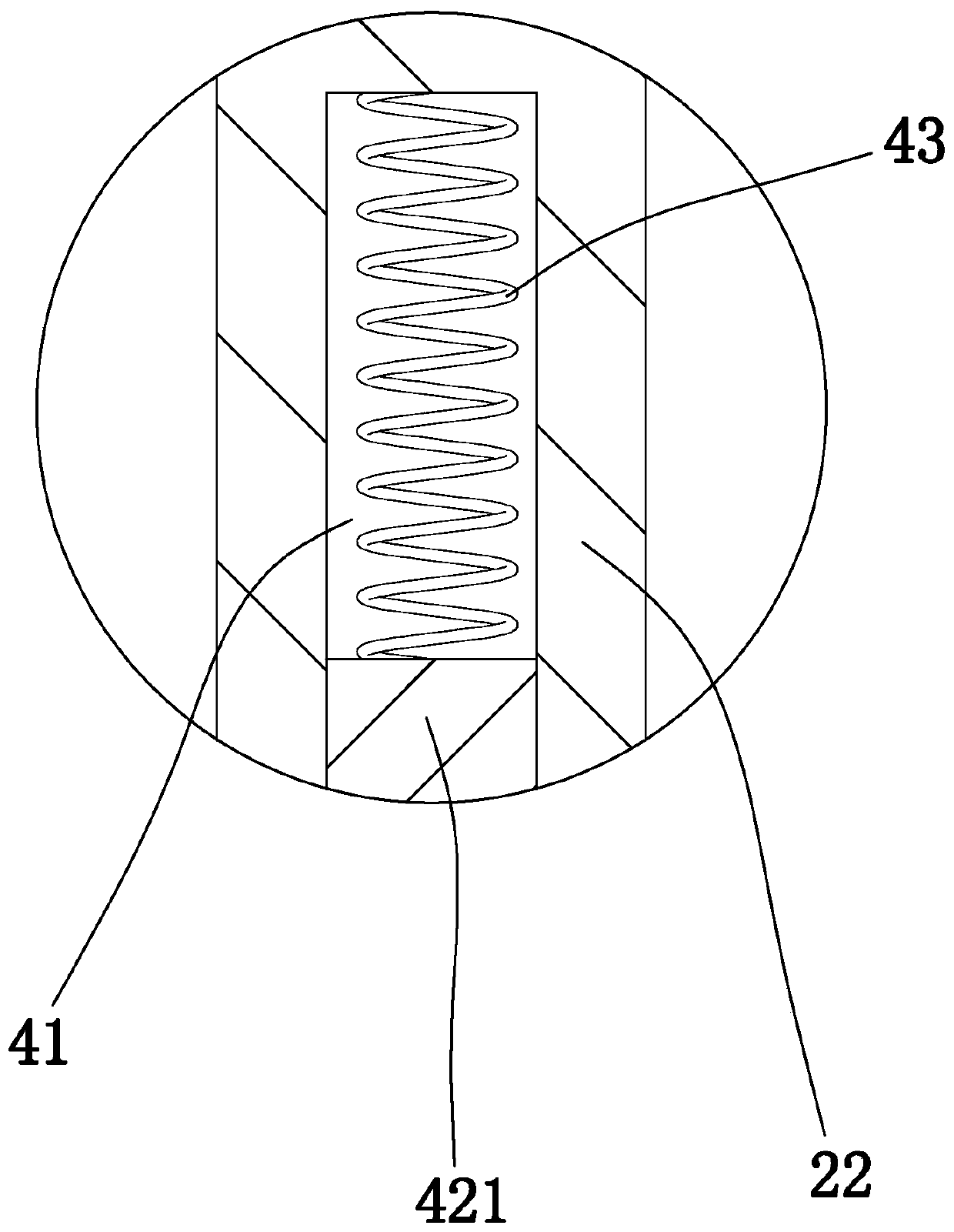
[0029] Embodiment 2: the basic structure and implementation mode of this embodiment are the same as embodiment 1, and its difference is, as Figure 2 to Figure 4 As shown in , the lower rod section is provided with a column groove 41 opening at the lower end of the lower rod section. The column groove is provided with a conductive ejector rod 42 that slides and fits with the column groove. The conductive ejector rod includes a rod body 421 and is used for the contact test. The conductive hemispherical head 422 of the metal part of the terminal row is provided with a spring 43 in the column groove, one end of the spring is connected to the lower rod section, and the other end of the spring is connected to the conductive ejector rod.
[0030] The column groove, the conductive mandrel and the spring are coaxially arranged, and in the axial direction of the conductive mandrel: the spring, the rod body and the conductive hemispherical head are arranged in sequence.
[0031] In this...
PUM
 Abstract
Description
Claims
Application Information
 - R&D
- Intellectual Property
- Life Sciences
- Materials
- Tech Scout
- Unparalleled Data Quality
- Higher Quality Content
- 60% Fewer Hallucinations
Browse by: Latest US Patents, China's latest patents, Technical Efficacy Thesaurus, Application Domain, Technology Topic, Popular Technical Reports.
© 2025 PatSnap. All rights reserved.Legal|Privacy policy|Modern Slavery Act Transparency Statement|Sitemap|About US| Contact US: help@patsnap.com


