Continuous wave radar system and method for detecting small low-altitude target

A small target and wave radar technology, which is applied in the field of target detection, can solve the problems of low flying height of low-altitude slow-speed small targets, high ground clutter intensity, and many interference targets, and achieves low-speed target detection performance. Small size effect

Active Publication Date: 2018-06-22
XIDIAN UNIV
View PDF21 Cites 10 Cited by
  • Summary
  • Abstract
  • Description
  • Claims
  • Application Information

AI Technical Summary

Problems solved by technology

[0004] (1) The radar cross-sectional area (RCS) of low-altitude and slow-moving small targets is small, the signal echo is weak, the signal-to-noise ratio is low, and detection is difficult. Effective weak signal detection methods must be used
[0005] (2) The antenna beam points to the low altitude (or is in the working state of looking down), the ground clutter intensity is large, the range is wide, and the situation is complicated: there are major technical bottlenecks in the detection of low, small, and slow targets in the background of non-uniform clutter, and the radar reception The machine needs to have a large dynamic range, and the signal processing needs to have a strong clutter suppression ability
[0006] (3) There are many interference targets: because the low-altitude, slow-moving and small targets fly at a low altitude, it is inevitable that the radar will detect ground moving targets (mainly ground moving vehicles) at the same time when detecting them.

Method used


Image

  • Continuous wave radar system and method for detecting small low-altitude target
  • Continuous wave radar system and method for detecting small low-altitude target
  • Continuous wave radar system and method for detecting small low-altitude target

Examples


Embodiment Construction

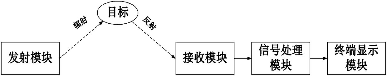
[0041] refer to figure 1 , which is a block diagram of a continuous wave radar system for low-altitude small target detection of the present invention; wherein the continuous wave radar system for low-altitude small target detection includes a transmitting module, a receiving module, a signal processing module and a terminal display module; The output end of the transmitting module radiates the linear frequency modulation continuous wave outwards, and enters the input end of the receiving module after being reflected by the target, the output end of the receiving module is connected to the input end of the signal processing module, and the output end of the signal processing module is connected to the input end of the terminal display module; Slow and small targets are all called low-altitude, slow-speed, and small-scale flying targets. The flying altitude is generally below 1,000 meters, the speed is relatively slow, and the radar reflection area is small.

[0042]The transmi...


PUM


Abstract

The invention discloses a continuous wave radar system for detecting a small low-altitude target. A transmission module is used for generating and radiating out linear frequency-modulation continuouswaves; after the radiated linear frequency-modulation continuous waves are reflected by the target, an echo signal which is reflected by the target is obtained; a receiving module is used for receiving the echo signal which is reflected by the target, and Z intermediate frequency signals are obtained and sent to a signal processing module; the signal processing module is used for receiving the Z intermediate frequency signals which are sent by the receiving module to obtain a real small low-altitude target point trace and sending the real small low-altitude target point trace to a terminal display module for display; the signal processing module is further used for obtaining Z low-pass filtering digital signals, conducting parameter estimation according to the real small low-altitude target point trace to obtain pitching angle and azimuthal angle information of the real small low-altitude target and then sending the pitching angle and azimuthal angle information of the real small low-altitude target to the terminal display module for display.

Description

technical field [0001] The invention relates to the technical field of target detection, in particular to a continuous wave radar system and method for low-altitude small target detection, which is suitable for the detection of low-altitude slow-speed small targets in complex environments. Background technique [0002] The opening of low-altitude airspace has put forward new requirements for ground military and civilian surveillance radar target detection. At present, my country has no effective means for low-altitude target surveillance, which cannot meet the basic needs of low-altitude air traffic control, air defense and security, and urgently needs to be solved; The rapid development and wide application of low-altitude, slow-moving and small-target technology represented by drones has brought new challenges to national security. There is an urgent need for effective monitoring of low-altitude, slow-moving and small targets such as drones for security and regional flight b...

Claims


Application Information

Patent Timeline
Patent Type & Authority Applications(China)
IPC IPC(8): G01S13/88G01S7/02G01S7/282G01S7/285G01S7/41
CPCG01S7/02G01S7/282G01S7/285G01S7/41G01S13/88
Inventor 赵永波刘宏伟张德华何学辉苏洪涛苏涛
Owner XIDIAN UNIV
Why Eureka
Try Eureka