
Protecting device for water-injection wellhead equipment

A protective device and equipment technology, which is applied in the direction of wellbore/well components, production fluid, earthwork drilling and production, etc. It can solve the problems that fine sand is easy to enter, cannot operate, and affects the normal operation of oil and gas wells, so as to avoid economic losses and avoid fire effect

Active Publication Date: 2018-06-26
PETROCHINA CO LTD
View PDF8 Cites 0 Cited by
  • Summary
  • Abstract
  • Description
  • Claims
  • Application Information

AI Technical Summary

Problems solved by technology

[0004] In order to solve the problem that the water injection wellhead equipment is exposed at the wellhead of the oil and gas well in the prior art, the parts of the water injection wellhead equipment are frequently stolen, and when the external environment is more sandy, fine sand is easy to enter the instrument or valve of the water injection wellhead equipment , affect the work of the instruments and valves of the water injection wellhead equipment, or when the outside temperature is low, the instruments or valves on the water injection wellhead equipment may fail to operate, and when the freezing situation is serious, it may also affect the oil and gas wells. Normal operation will cause huge economic losses, the embodiment of the present invention provides a protection device for water injection wellhead equipment

Method used


Image

  • Protecting device for water-injection wellhead equipment
  • Protecting device for water-injection wellhead equipment
  • Protecting device for water-injection wellhead equipment

Examples


Embodiment Construction

[0036] In order to make the object, technical solution and advantages of the present invention clearer, the implementation manner of the present invention will be further described in detail below in conjunction with the accompanying drawings.

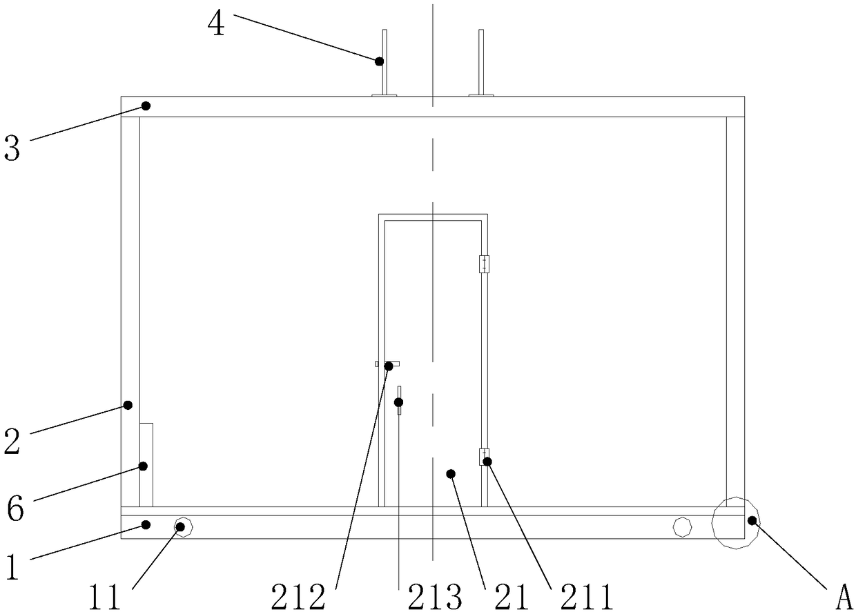
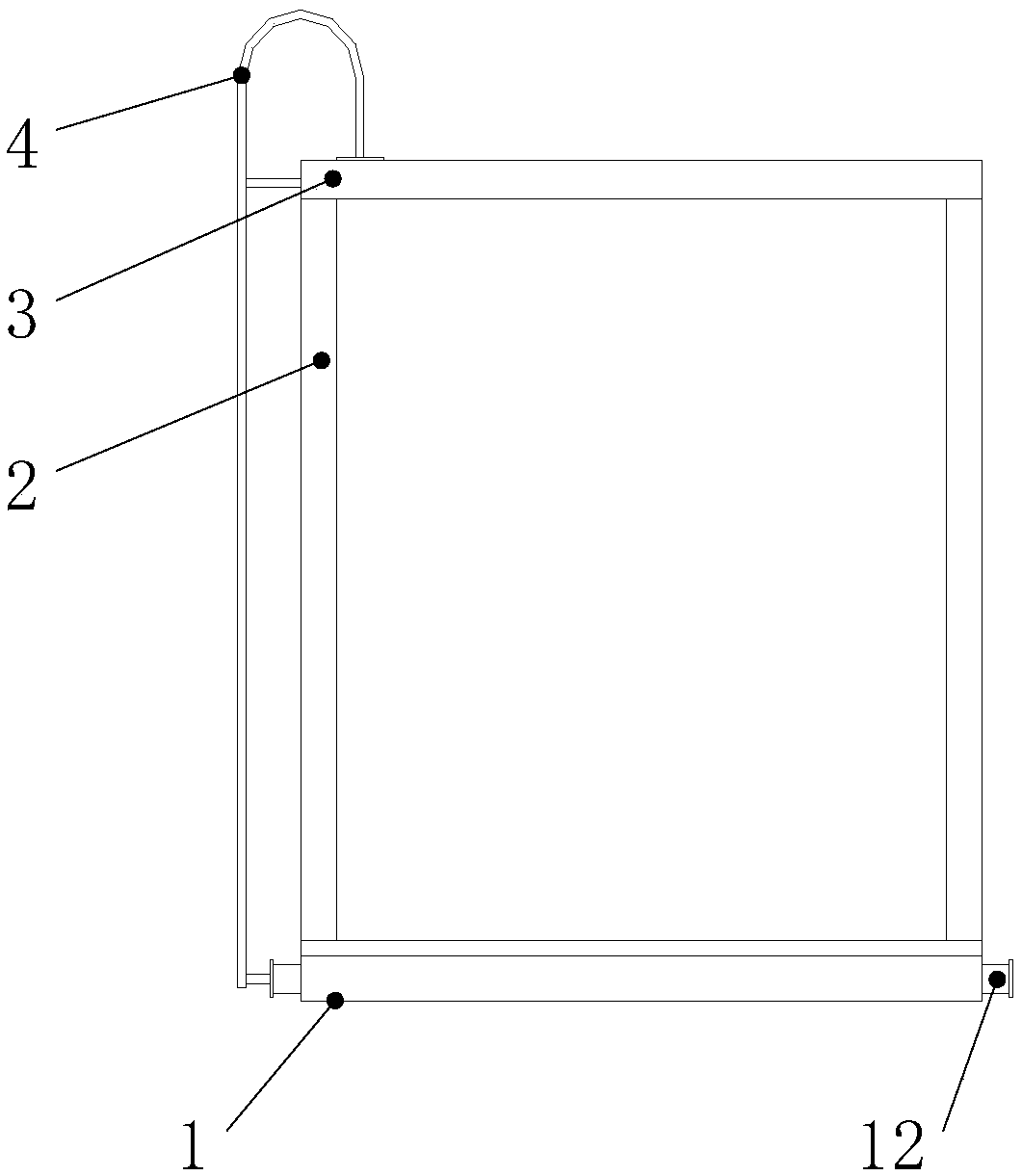
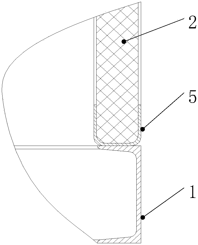
[0037] Such as figure 1 shown, combined with figure 2 To illustrate, the embodiment of the present invention provides a protective device for water injection wellhead equipment, the protective device for water injection wellhead equipment covers the outside of the water injection wellhead equipment, which includes: bottom ring beam 1, wall body 2, top cover 3 and ladder 4 ;

[0038] The bottom ring beam 1 is fixed on the foundation of the target oil and gas well, and four lifting holes 11 are provided on the outer wall of the bottom ring beam 1, and the four lifting holes 11 are divided into two groups, and the two groups of lifting holes 11 are respectively set on the bottom ring beam 1 on a set of opposite outer walls, and symmetr...


PUM


Abstract

The invention discloses a protecting device for water-injection wellhead equipment and belongs to the field of oil and gas exploitation. The water-injection wellhead equipment is covered with the protecting device for the water-injection wellhead equipment, and the protecting device for the water-injection wellhead equipment comprises a bottom ring beam, a wall body, a top cover and a crawling ladder. The protecting device for the water-injection wellhead equipment is formed by the bottom ring beam, the wall body, the top cover and the crawling ladder. The water-injection wellhead equipment iscovered with the protecting device for the water-injection wellhead equipment, parts of the water-injection wellhead equipment can be prevented from being stolen by others, and the situation that when wind sand of the outside world is serious, the fine sand enters instruments or valves of the water-injection wellhead equipment, and thus work of the instruments or the valves of the water-injectionwellhead equipment is influenced can be prevented. The wall body and the top cover are each made of a material with the fire-resistance and heat-preservation functions, thus the situation that when the temperature of the outside world is low, the instruments or the valves or the like on the water-injection wellhead equipment are out of order or damaged can be prevented, accordingly, normal operation of an oil and gas well is prevented from being influenced, the economic loss is avoided, and the situation that when the outside world is on fire, the water-injection wellhead equipment is on firecan be avoided.

Description

technical field [0001] The invention relates to the field of oil and gas exploitation, in particular to a protection device for water injection wellhead equipment. Background technique [0002] Water injection is a commonly used reservoir stimulation method in the development of oil and gas fields. It injects water into the oil and gas wells through the water injection wellhead equipment installed at the wellhead of the oil and gas wells to make up for the underground deficit caused by the recovery of crude oil, supplement the energy of the formation, and improve the oil recovery rate and The recovery rate, thereby stabilizing the production capacity of oil and gas wells. [0003] The current water injection wellhead equipment is all exposed at the wellhead of oil and gas wells, and the parts of the water injection wellhead equipment are frequently stolen, and because the external environment is relatively harsh, when the external environment is more sandy, fine sand is easy...

Claims


Application Information

Patent Timeline
Patent Type & Authority Applications(China)
IPC IPC(8): E21B43/20E21B33/03
CPCE21B33/03E21B43/20
Inventor 薛多山王增斋陆蒙湘史志峰冯自青
Owner PETROCHINA CO LTD
Learn More