Rapid on-site vertical lifting bed fence

A lifting bed and in-situ technology, which is applied in the direction of children's beds, children's furniture, household appliances, etc., can solve the problems of poor stability, inconvenient lifting bed fence, etc., and achieve the effect of safe lifting

Active Publication Date: 2018-06-29
瞿静
View PDF8 Cites 1 Cited by
  • Summary
  • Abstract
  • Description
  • Claims
  • Application Information

AI Technical Summary

Problems solved by technology

[0009] In order to carry out rapid lifting, and aiming at the inconvenient and poor stability of operating the lifting bed fence at a single position in the background technology, the present invention proposes a fast in-situ vertical lifting bed fence, which is characterized in that it includes: a lifting Rod, two leading rods, two secondary guide rods, manual switch device, locking device, transmission positioning device, two pairs of fixed rod groups, two upright columns, bottom frame rod, two pipe joints and a piece of mesh cloth; The tightening device is installed at the left and right ends of the lifting rod; the manual switch device is installed in the middle of the lifting rod, the manual switch device and the locking device are connected through the transmission positioning device, the main rod and the secondary guide rod pass through the positioning hole outside the transmission positioning device and Make the lifting rod slide up and down freely along the axis of the column;

Method used


Image

  • Rapid on-site vertical lifting bed fence
  • Rapid on-site vertical lifting bed fence
  • Rapid on-site vertical lifting bed fence

Examples


Embodiment 4

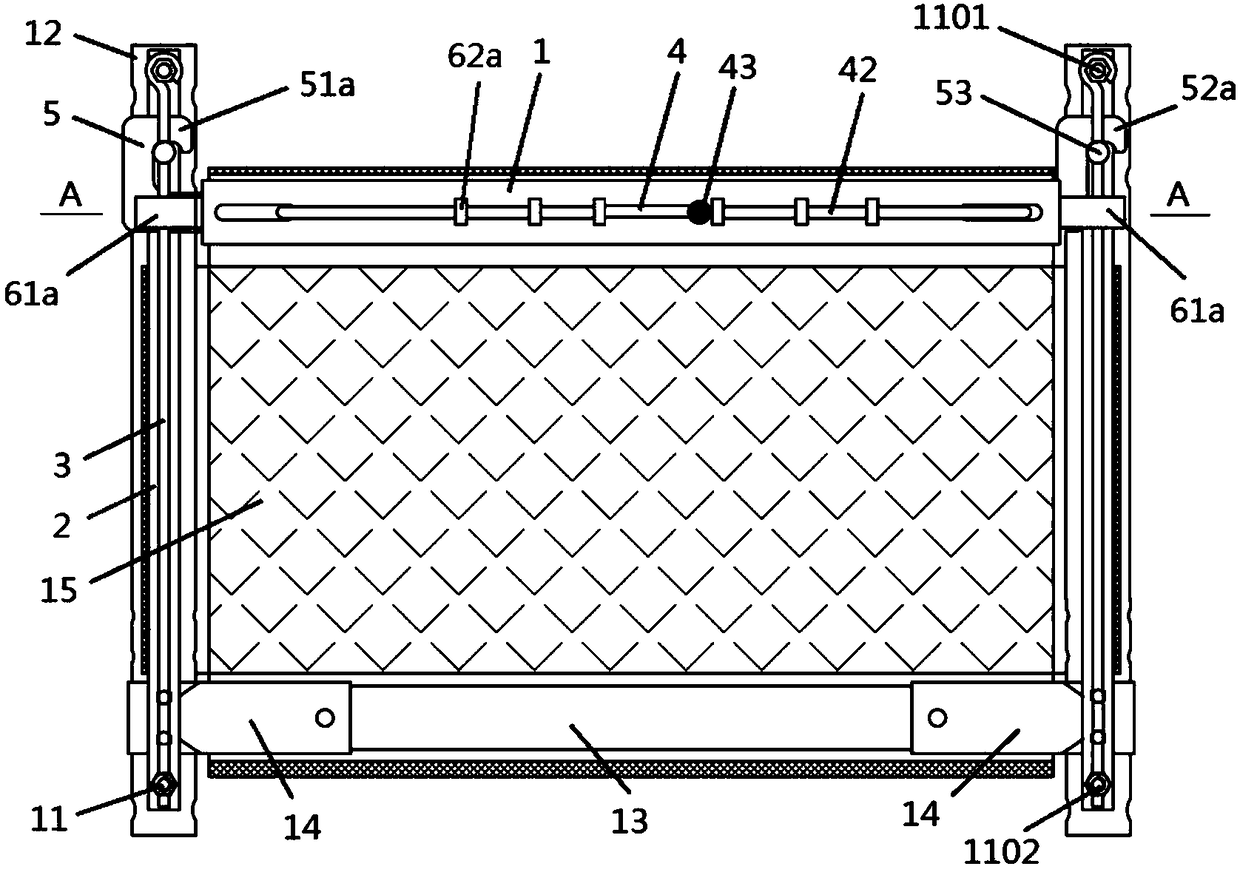
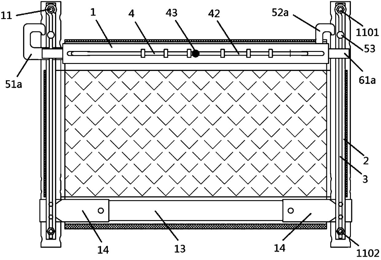
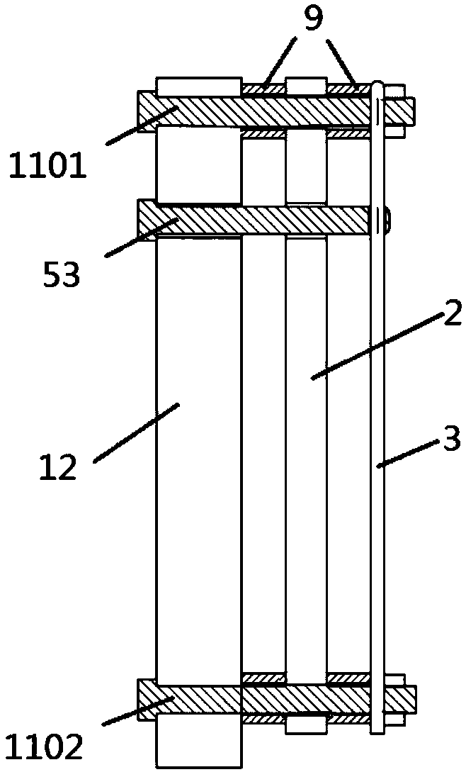
[0101] Such as Figure 13 Up to Embodiment 4 of the present invention shown in Figure 15, the description of the same part as Embodiment 1 in this embodiment is omitted below, and only the structure different from Embodiment 1 is described here;

[0102] The upper fixed rod 1101 and the lower fixed rod 1102 installed on the same column 12 have the same orientation, and each has two mounting holes for installing the main rod 2 and the secondary guide rod 3. The upper and lower ends are respectively installed on the upper fixed rod 1101 and the lower fixed rod 1102 through the mounting holes, and the diameters of the main rod 2 and the secondary guide rod 3 are the same; in this embodiment, no pad 9 is provided;

[0103] The manual switch device 4 includes a rotating handle 44, a rotating shaft and a handle return spring 411. The rotating handle 44 is installed outside the lifting rod 1 through a rotating shaft. On the straight face; the two ends of the handle return spring 411...

Embodiment 5

[0110] Such as Figure 14a and 14b In the illustrated embodiment 5 of the present invention, the description of the same part as the embodiment 4 in the present embodiment is omitted below, and only the structure different from the embodiment 4 is described here;

[0111] The transmission positioning device 6 comprises two steel wire sleeves 64 and two steel wires 63 installed in the two steel wire sleeves;

[0112] Manual switch device 4 comprises: No. 1 switch push rod 45e, slide rail 46, slide block 47, No. 1 switch push block 48e, No. 1 push block groove 49e and first switch housing 410e; Wherein, by upper rectangular half shell and The first switch casing 410e, which is composed of the upper and lower isosceles trapezoidal half shells in the lower part, is installed outside the lifting rod 1, and the left and right two steel wire sleeves 64 pass through the holes at the left and right ends of the first switch casing 410e, so that the two steel wires 63 can enter the firs...

Embodiment 6

[0118] Such as Figure 15a and 15b In the illustrated embodiment 6 of the present invention, the description of the same part as the embodiment 4 in the present embodiment is omitted below, and only the structure different from the embodiment 4 is described here;

[0119] The transmission positioning device 6 comprises two steel wire sleeves 64 and two steel wires 63 installed in the two steel wire sleeves;

[0120]Manual switch device 4 comprises: No. 2 switch push rod 45f, No. 2 switch push block 48f, No. 2 push block groove 49f and second switch shell 410f; The second switch housing 410f is installed outside the lifting rod 1, and the left and right two steel wire sleeves 64 pass through the holes at the left and right ends of the second switch housing 410f, so that the two steel wires 63 can enter the second switch housing 410f; the second switch housing 410f There is No. 2 push block groove 49f in the bottom surface along the symmetrical axis. No. 2 switch push block 48...


PUM


Abstract

The invention discloses a rapid on-site vertical lifting bed fence. The fence comprises a lifting rod, a primary and secondary guide rod, a manual on-off device, a locking device, a transmission positioning device, a fixed rod set, stand posts and a mesh cloth, wherein the two stand posts are respectively arranged on two ends of one side of a bed, a pair of fixed rod sets are arranged on the outerside of each stand post, and the primary and secondary guide rod is arranged on the fixed rod set; the rectangular mesh cloth is sheathed on the lifting rod, a bottom frame rod at the bottom of the stand posts, and the main guide rods on two sides; the locking devices are arranged on the left end and the right end of the lifting rod; and the manual on-off device is arranged in the middle of the lifting rod, the manual on-off device and the locking devices are connected through the transmission positioning device arranged on the lifting rod, and the lifting rod can freely slide up and down inthe axial direction of the stand posts. The rapid on-site vertical lifting bed fence overcomes the defects that the traditional vertical lifting bed fence is complicated to lift and overlow in efficiency, prevents an operator from running between the two stand posts, and rapid, convenience and safe lifting of the fence can be realized only by simply operating the pull rod in the middle of the lifting rod.

Description

technical field [0001] The invention relates to the technical field of bed accessories, in particular to a fast in-situ vertical lift bed fence. Background technique [0002] The lifting process of the fence of the children's bed traditionally installed on the adult bed is cumbersome, and the operator needs to walk back and forth between the two uprights; the traditional fence is equipped with a hook type, a latch type, or a protrusion that can be pressed at both ends of the lifting rod, etc. Locking parts, the operator needs to go to both ends of the lifting rod and manually unlock the locking parts to put down the fence. These designs make the bed fence lifting not convenient and fast enough, poor in operability, and cannot achieve fast lifting. The columns, bottom frames, and guide rods used The catastrophic consequences of bolts loosening and falling out, and the loud noise that occurs when the bump is pressed or the ring slides off for a split second. [0003] Therefor...

Claims


Application Information

Patent Timeline
Patent Type & Authority Applications(China)
IPC IPC(8): A47D7/00A47D15/00
CPCA47D7/00A47D15/008
Inventor 瞿静
Owner 瞿静
Why Eureka
Try Eureka