Inferior vena cava temporary filter

A filter and vena cava technology, which is applied in the fields of filters in blood vessels, medical science, prostheses, etc., can solve the problems that the recovery head is easy to stick to the blood vessel wall, and the single-layer filter effect of the filter is poor, so as to achieve simple and convenient operation, increase intensity effect

Active Publication Date: 2018-06-29
GENERAL HOSPITAL OF PLA
View PDF7 Cites 1 Cited by
  • Summary
  • Abstract
  • Description
  • Claims
  • Application Information

AI Technical Summary

Problems solved by technology

[0006] In order to overcome the problems of the conical thrombus filter in the prior art, the recovery head is easy to stick to the blood vessel wall, and the single-layer filter effect of the filter is poor, the present invention provides a temporary filter for inferior vena cava

Method used


Image

  • Inferior vena cava temporary filter
  • Inferior vena cava temporary filter
  • Inferior vena cava temporary filter

Examples


Embodiment 1

[0048] Embodiment 1 A kind of inferior vena cava temporary filter

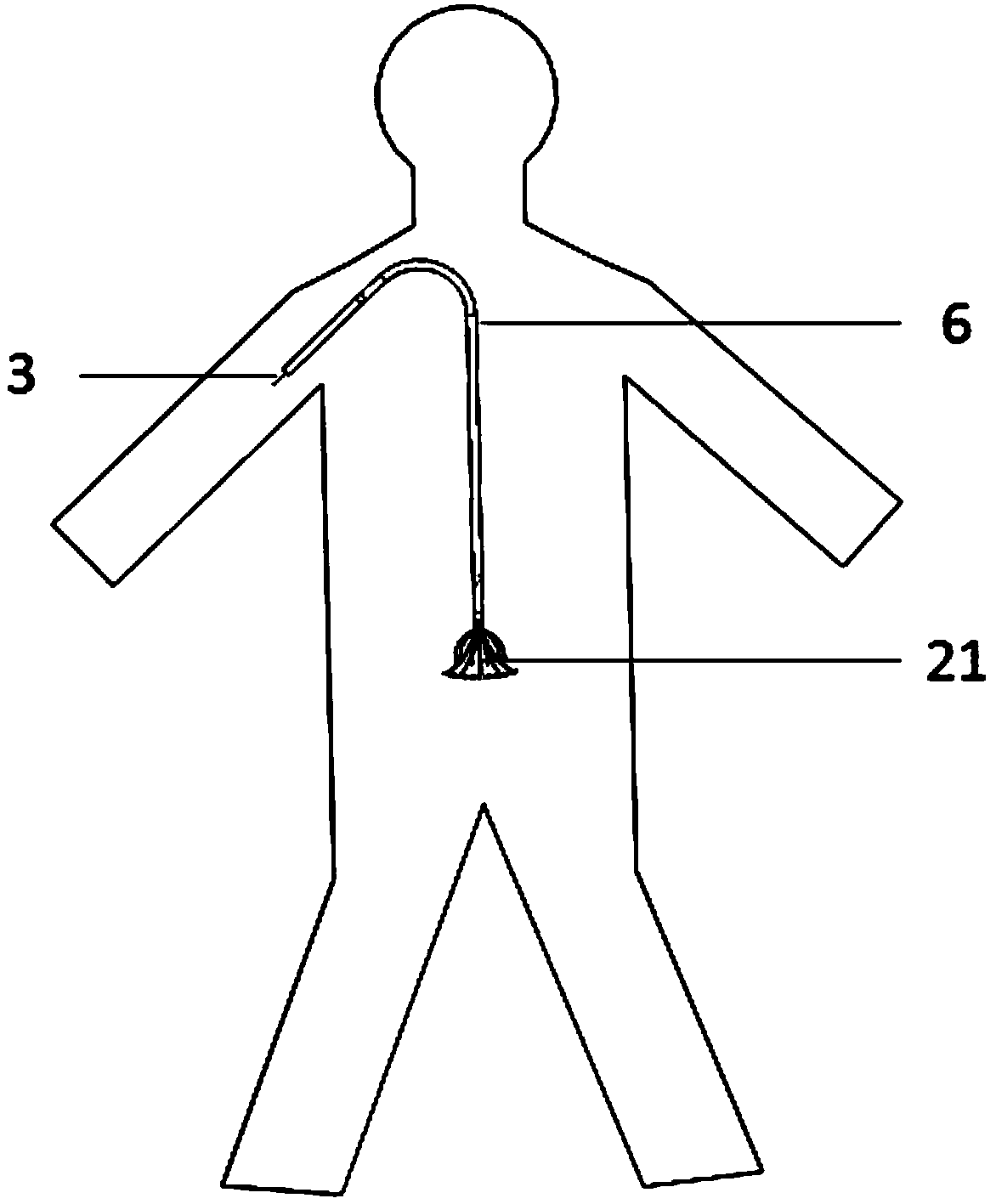
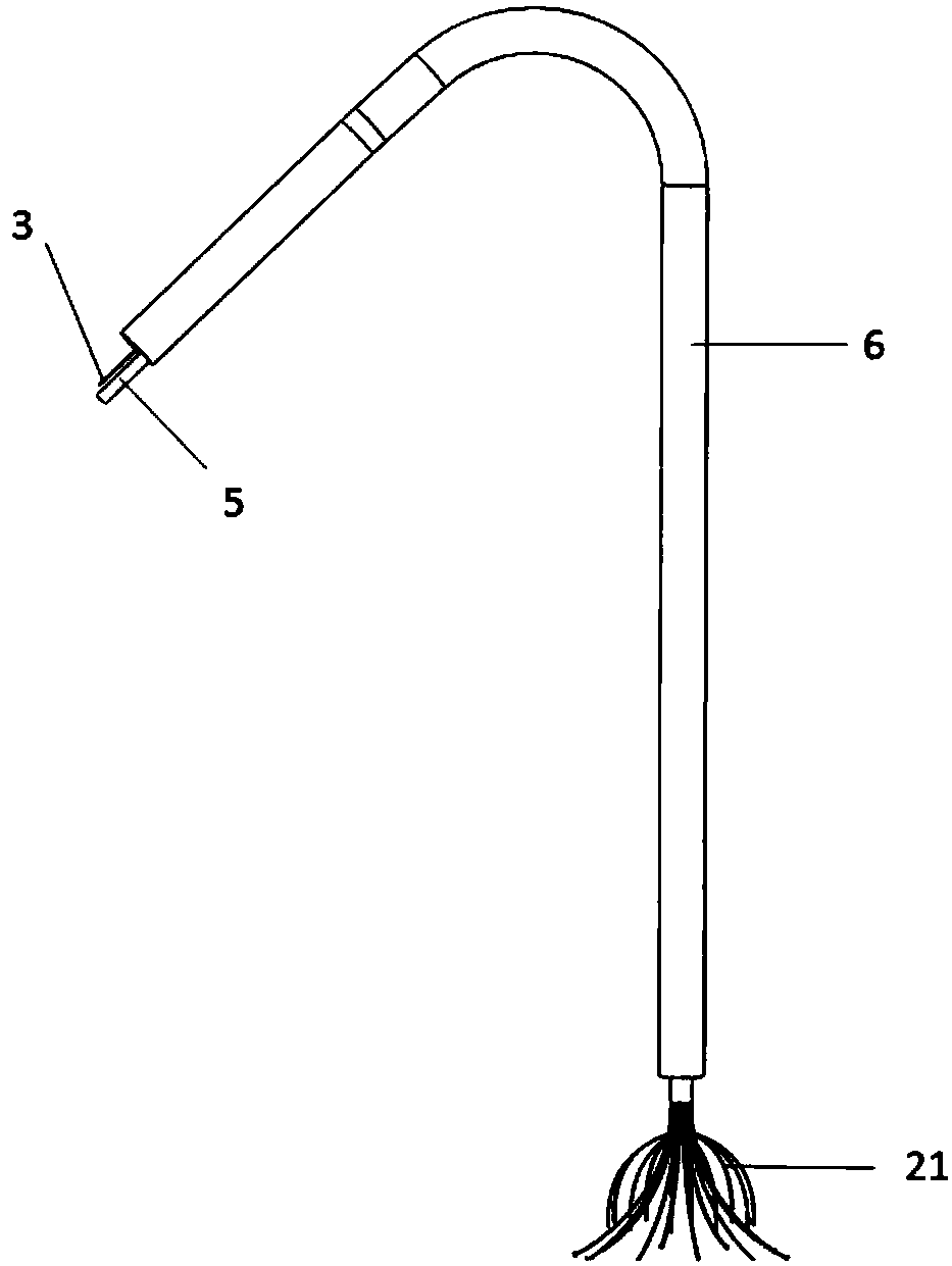
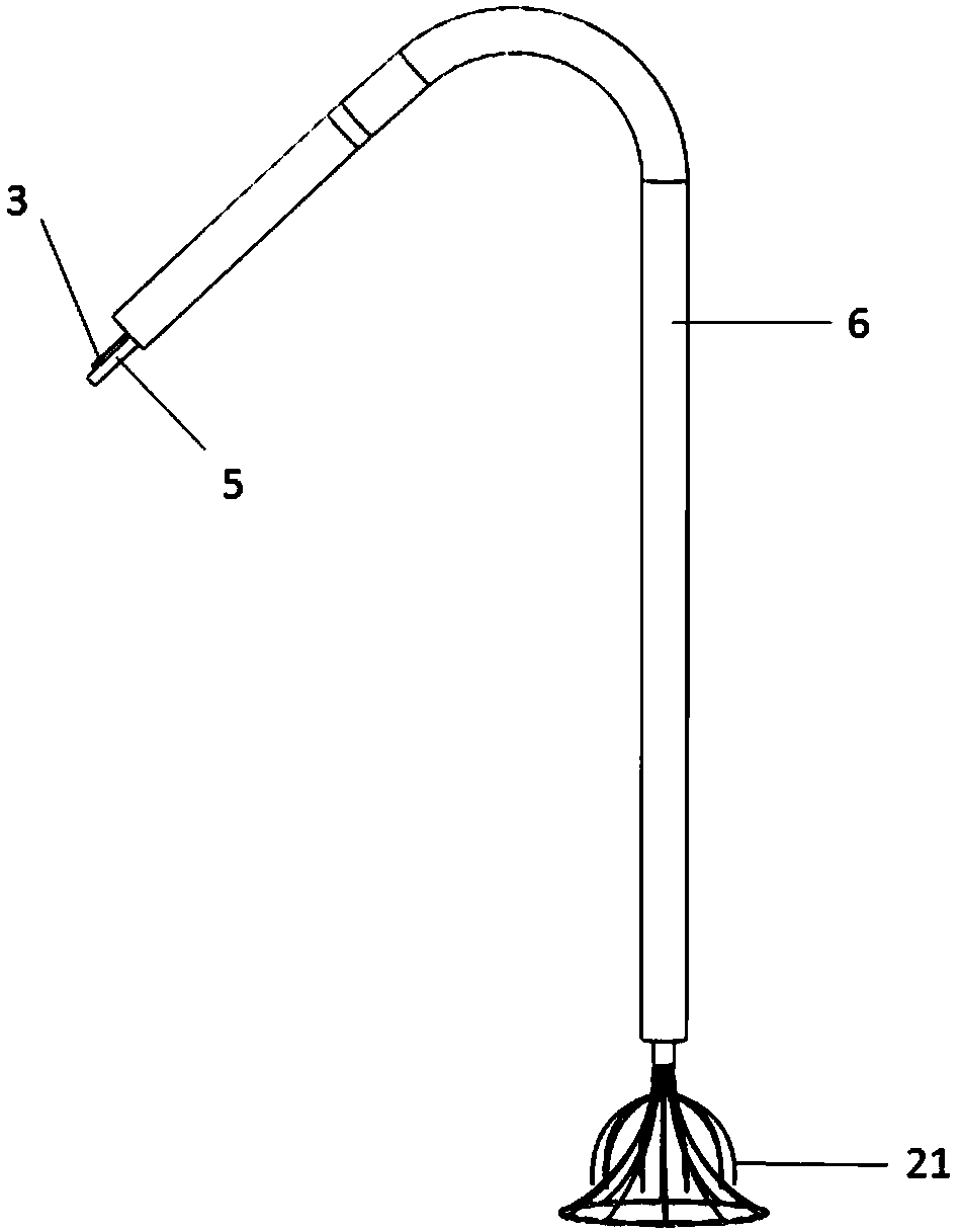
[0049] A temporary filter for inferior vena cava, which includes a lower filtering structure and an upper recovery rod 1, characterized in that a hanging wire structure is set on the recovery rod 1, and a long pulling wire 3 is arranged at the hanging wire structure, and a long pulling wire 3 is arranged on the hanging wire structure. The other end of the pull wire 3 is free; the outside of the long pull wire 3 is provided with a sleeve 6 structure, and a push rod 5 that pushes the recovery rod 1 to push out the filter structure is also arranged in the sleeve 6; the long pull wire 3 and the sleeve The length of the tube 6 can ensure that the long puller wire 3 is set inside the cannula 6 and is placed outside the body together with the rearmost end of the cannula 6, while the other parts of the sleeve 6 and the long puller wire 3 are set inside the blood vessel. 3 outside. The wire hanging structure is an obl...

Embodiment 2

[0051] Embodiment 2 A kind of inferior vena cava temporary filter

[0052] A temporary filter for inferior vena cava, which includes a lower filtering structure and an upper recovery rod 1, characterized in that a hanging wire structure is set on the recovery rod 1, and a long pulling wire 3 is arranged at the hanging wire structure, and a long pulling wire 3 is arranged on the hanging wire structure. The other end of the pull wire 3 is free; the outside of the long pull wire 3 is provided with a sleeve 6 structure, and a push rod 5 that pushes the recovery rod 1 to push out the filter structure is also arranged in the sleeve 6; the long pull wire 3 and the sleeve The length of the tube 6 can ensure that the long puller wire 3 is set inside the cannula 6 and is placed outside the body together with the rearmost end of the cannula 6, while the other parts of the sleeve 6 and the long puller wire 3 are set inside the blood vessel. 3. The outside hanging wire structure is a long ...

Embodiment 3

[0054] Embodiment 3 A kind of inferior vena cava temporary filter

[0055] A temporary filter for inferior vena cava, which includes a lower filtering structure and an upper recovery rod 1, characterized in that a hanging wire structure is set on the recovery rod 1, and a long pulling wire 3 is arranged at the hanging wire structure, and a long pulling wire 3 is arranged on the hanging wire structure. The other end of the pull wire 3 is free; the outside of the long pull wire 3 is provided with a sleeve 6 structure, and a push rod 5 that pushes the recovery rod 1 to push out the filter structure is also arranged in the sleeve 6; the long pull wire 3 and the sleeve The length of the tube 6 can ensure that the long puller wire 3 is set inside the cannula 6 and is placed outside the body together with the rearmost end of the cannula 6, while the other parts of the sleeve 6 and the long puller wire 3 are set inside the blood vessel. 3 outside. The wire hanging structure is a long...


PUM


Abstract

An interior vena cava temporary filter comprises a filtering structure on the lower portion and a recycling rod on the upper portion, and is characterized in that the recycling rod is provide with a wire hanging structure, a long traction wire is arranged at the position of the wire hanging structure, and the other end of the long traction wire is free; a sleeve structure is arranged on the outerside of the long traction wire, and a push rod which pushes out of the filtering structure by pushing the recycling rod is further arranged in a sleeve; the lengths of the long traction wire and the sleeve can ensure that the long traction wire is arranged in the sleeve and the long traction wire and the rear end of the sleeve are arranged in vitro; the sleeve and the other portions of the long traction wire are arranged in blood vessels. The wire hanging structure is a combination of an oblique notch or a traction wire ring; and the filter is a conical filtering structure, a spindle-shaped filtering structure or a crease mark filtering structure. The long traction wire is arranged on the filter, the recycling rod can be effectively prevented from being inclined, and because the long traction wire is fixed in vitro, the long traction wire can be convenient to collect after being used; and by the filtering structure consisting of multiple crease marks, the purpose of adjusting the interior vena cava temporary filter according to the circumstance of the sizes of blood vessels of a patent can be achieved.

Description

technical field [0001] The invention belongs to medical devices in the field of interventional radiation, in particular to a thrombus filtering device inserted into the inferior vena cava to prevent pulmonary embolism, in particular to a temporary filter for the inferior vena cava. Background technique [0002] Pulmonary embolism (referred to as Pulmonary Embolism, PE) refers to the clinical and pathophysiological syndrome of pulmonary circulation disorder caused by endogenous or exogenous emboli blocking the pulmonary artery or its branches; severe cases may cause sudden death. Emboli usually originate from the deep veins of the lower extremities and pelvis, causing embolism by circulation to the pulmonary arteries; but rarely originate from the veins of the upper extremities, head, and neck. Studies have shown that deep veins originating from the lower extremities and pelvis account for 60%-90% of the sources of emboli. Therefore, a thrombus filter can be placed below the...

Claims


Application Information

Patent Timeline
Patent Type & Authority Applications(China)
IPC IPC(8): A61F2/01
CPCA61F2/01A61F2/011A61F2002/016
Inventor 刘凤永袁宏军管阳李鑫左太阳付金鑫王茂强
Owner GENERAL HOSPITAL OF PLA
Why Eureka
Try Eureka