Suction cup type rail cleaning device

A cleaning device and suction cup technology, which is applied in the field of rail cleaning devices and suction cup cleaning devices, can solve problems such as inconvenient use, complicated structure, and insufficient thoroughness.

Active Publication Date: 2020-12-08
山东远腾环保设备有限公司
View PDF1 Cites 0 Cited by
  • Summary
  • Abstract
  • Description
  • Claims
  • Application Information

AI Technical Summary

Problems solved by technology

The rails are exposed to the outdoors all the year round and are polluted by the external environment, so they need to be cleaned regularly. However, the track cleaning vehicles on the market are often expensive, complicated in structure and inconvenient to use, and they cannot clean the small gaps in the joints of the rails well. Therefore, there is a rail cleaning device on the market, such as "a rail cleaning device whose announcement number is CN201520456832.4, which relates to the field of railway maintenance and includes a cleaning box and a driving device. The lower surface of the cleaning box is provided with a suction There is a suction fan inside the cleaning box, and a connecting pipe is installed between the suction fan and the dust suction port. There is a partition baffle inside the cleaning box, and a through hole is provided at the bottom of the connecting pipe on the right side of the partition baffle The bottom of the cleaning box is provided with a slideway, and the inside of the slideway is provided with a cleaning brush and a push rod brush connected with a push rod motor. The pushing device includes a U-shaped push handle and a telescopic connecting rod. There are fixed bolts, and the U-shaped push handle is connected with the cleaning box through a telescopic connecting rod. The utility model provides a rail cleaning device with simple structure, low cost and easy use, which can clean gaps. Relatively firm dirt, not easy to remove, not thorough enough

Method used


Image

  • Suction cup type rail cleaning device
  • Suction cup type rail cleaning device
  • Suction cup type rail cleaning device

Examples


Embodiment Construction

[0019] Referring to the accompanying drawings, through the description of the embodiments, the specific embodiments of the present invention include the shape, structure, mutual position and connection relationship of each part, the function and working principle of each part, and the manufacturing process of the various components involved. And the method of operation and use, etc., are described in further detail to help those skilled in the art have a more complete, accurate and in-depth understanding of the inventive concepts and technical solutions of the present invention.

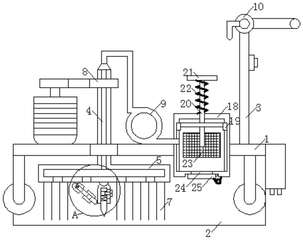
[0020] A sucker type rail cleaning device, comprising a base plate 1, the front and rear ends of the base plate 1 are provided with downward baffle plates 2, and the opposite end faces of the two baffle plates 2 are respectively against the front and rear end faces of the rail, the upper end of the base plate 1 is on the right The side is connected with an upward support rod 3, and the upper end of th...


PUM


Abstract

The invention discloses a suction cup type rail cleaning device which comprises a bottom plate. Bristles are located outside a scraper. The upper end of the circumference of a rotating pipe is sleevedwith a driven belt wheel which is connected with a driving belt wheel through a belt. The driving belt wheel is connected with a motor which is fixed to the upper end of the bottom plate. The upper end of the rotating pipe is connected with a soft gas guide pipe through a mechanical sealing element. The other end of the gas guide pipe is connected with an exhaust fan. A storage battery is arranged on the bottom plate. A switch is arranged on a supporting rod and electrically connected with the storage battery. The switch is electrically connected with the motor and the exhaust fan. When a rotating plate rotates, the scraper can be driven to rotate; by arranging a first spring and a second spring, the scraper has toughness, the squeezing force is ensured by means of the first spring, and it is ensured through the second spring that the scraper can incline and be prevented from getting stuck when encountering a hard object; dirt scrapped away can be sucked away by the rotating plate andenter a dustproof box, and therefore cleaning is thorough.

Description

technical field [0001] The invention belongs to the technical field of rail cleaning, and relates to a rail cleaning device, in particular to a suction cup type rail cleaning device. Background technique [0002] Railway tracks, referred to as rails, rails, tracks, etc., are used on railways and cooperate with switchers to allow trains to walk without turning. The track is usually composed of two parallel steel rails. The rails are fixed on the sleepers, and the ballast is under the sleepers. The rails made of steel can bear greater weight than other materials. Sleepers, also known as sleepers, or road sleepers, function to separate and distribute the weight of the rails, keep the rails fixed, and maintain the gauge of the rails. Generally speaking, the bottom of the track is paved with gravel ballast, also known as ballast, crushed stone or ballast bed, which provides elasticity and drainage for the track. Tracks can also be laid on concrete bases (quite common on bridges...

Claims


Application Information

Patent Timeline
Patent Type & Authority Patents(China)
IPC IPC(8): E01H8/10
CPCE01H8/105
Inventor 张冬
Owner 山东远腾环保设备有限公司
Why Eureka
Try Eureka