Additional object for 3D printing object detection
An object detection and 3D printing technology, applied in the field of 3D printing, can solve the problems of repeated complete coincidence, rising cost, and difficulty in applying detection results, and achieve the effect of extremely high cost and low cost.
- Summary
- Abstract
- Description
- Claims
- Application Information
AI Technical Summary
Problems solved by technology
Method used
Image
Examples
Embodiment 1
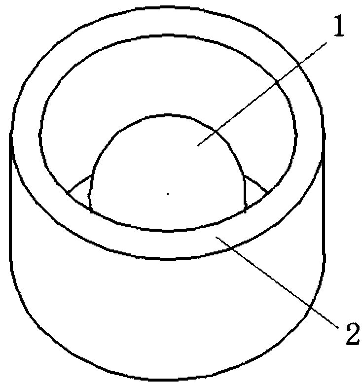
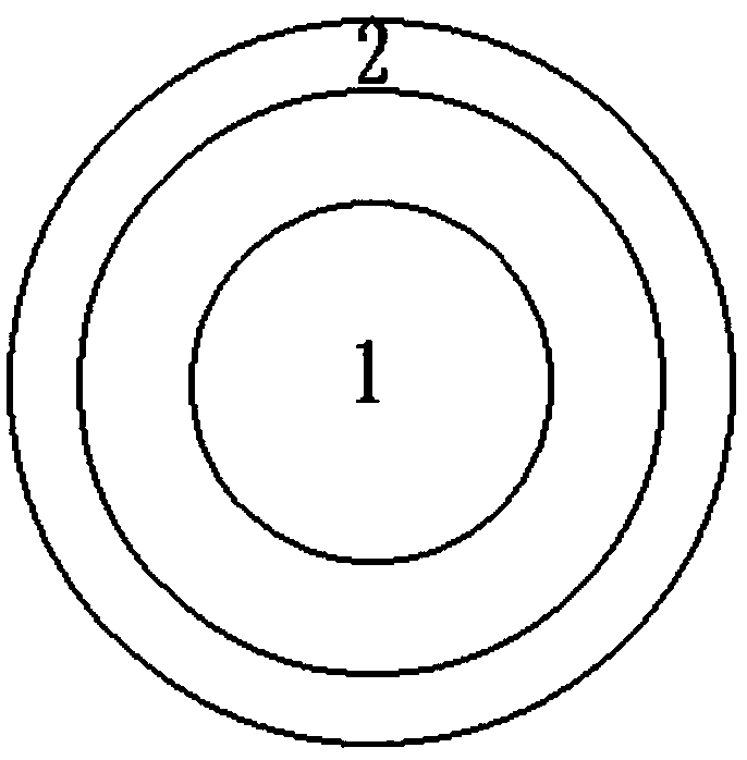
[0019] In this embodiment, the additional object 2 is arranged on the outer periphery of the object to be printed 1 without any contact between the additional object 2 and the object to be printed 1, wherein the additional object 2 is a hollow object transparent up and down .
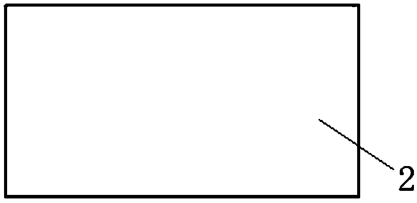
[0020] The additional object 2 is a structure surrounded by four vertical thin plates, wherein the thin plates are vertical thin plates printed in four directions: front, rear, left, right, of the object to be printed 1 . During the printing process, the temperature and other conditions of the printing area have a great influence on the printing result, so the actual situation of the printing area is partially reflected by printing such a structure surrounded by thin plates on each side. At the same time, the additional object 2 should completely cover the position prone to unexpected situations in the printing process to achieve the function of monitoring the whole process of the real printing process....
Embodiment 2
[0024] In this embodiment, the additional object 2 is arranged on the outer periphery of the object to be printed 1 without any contact between the additional object 2 and the object to be printed 1, wherein the additional object 2 is a hollow object transparent up and down .
[0025] When the object to be printed 1 has a regular shape structure, the inner surface structure of the additional object 2 is an enlarged body of the regular shape structure of the object to be printed 1 , and the magnification factor is greater than 1. In this embodiment, it is sufficient that the inner surface structure of the additional object 2 is slightly larger than the regular shape structure of the object to be printed 1, so that the additional object 2 does not directly contact the object to be printed 1, At the same time, the additional object 2 should completely cover the position prone to unexpected situations in the printing process to achieve the whole process of monitoring the real prin...
Embodiment 3
[0032] In this embodiment, the additional object 2 is arranged on the outer periphery of the object to be printed 1 without any contact between the additional object 2 and the object to be printed 1, wherein the additional object 2 is a hollow object transparent up and down .
[0033] When the object to be printed 1 has an irregular shape, the additional object 2 is a vertically arranged hollow cylinder, and the inner diameter of the hollow cylinder is larger than the maximum vertical diameter of the object to be printed 1 Projected diameter dimension. In this embodiment, it is enough that the inner diameter of the hollow cylinder is slightly larger than the maximum vertical projected diameter of the object to be printed 1 , so that the additional object 2 does not directly contact the object to be printed 1 . At the same time, the additional object 2 should completely cover the position prone to unexpected situations in the printing process to achieve the function of monitor...
PUM
 Abstract
Description
Claims
Application Information
 - R&D
- Intellectual Property
- Life Sciences
- Materials
- Tech Scout
- Unparalleled Data Quality
- Higher Quality Content
- 60% Fewer Hallucinations
Browse by: Latest US Patents, China's latest patents, Technical Efficacy Thesaurus, Application Domain, Technology Topic, Popular Technical Reports.
© 2025 PatSnap. All rights reserved.Legal|Privacy policy|Modern Slavery Act Transparency Statement|Sitemap|About US| Contact US: help@patsnap.com


