Combined split mounting type hoisting bracket and hoisting method

An assembled and hanger technology, applied in safety devices, transportation and packaging, load hanging components, etc., can solve the problems of high-altitude falling, high cost, poor versatility of components, and achieve the effect of enhancing versatility and ensuring hoisting safety.

Inactive Publication Date: 2018-06-29
SHANGHAI NO 7 CONSTR
View PDF5 Cites 3 Cited by
  • Summary
  • Abstract
  • Description
  • Claims
  • Application Information

AI Technical Summary

Problems solved by technology

When using the traditional steel shoulder pole for hoisting, since the steel shoulder pole has only two fixed lifting points, the versatility is poor. When hoisting prefabricated components of different specifications and types, it is necessary to frequently replace the hanger and hanger, which is costly, time-consuming and laborious, and the construction efficiency is low.
Moreover, the traditional spreader cannot meet the requirements of hoisting large-sized and heavy prefabricated components, and there is even a safety hazard that the lifting wire rope breaks and the component falls from a high altitude
In addition, the existing spreader does not have any monitoring and protection measures for the steel wire rope during hoisting, which cannot ensure the safety of hoisting

Method used


Image

  • Combined split mounting type hoisting bracket and hoisting method
  • Combined split mounting type hoisting bracket and hoisting method
  • Combined split mounting type hoisting bracket and hoisting method

Examples


Embodiment Construction

[0023] The present invention will be further described in detail below in conjunction with the accompanying drawings and specific embodiments. According to the following description, the purpose, technical solution and advantages of the present invention will be more clear. It should be noted that the described embodiments are preferred embodiments of the present invention, but not all embodiments.

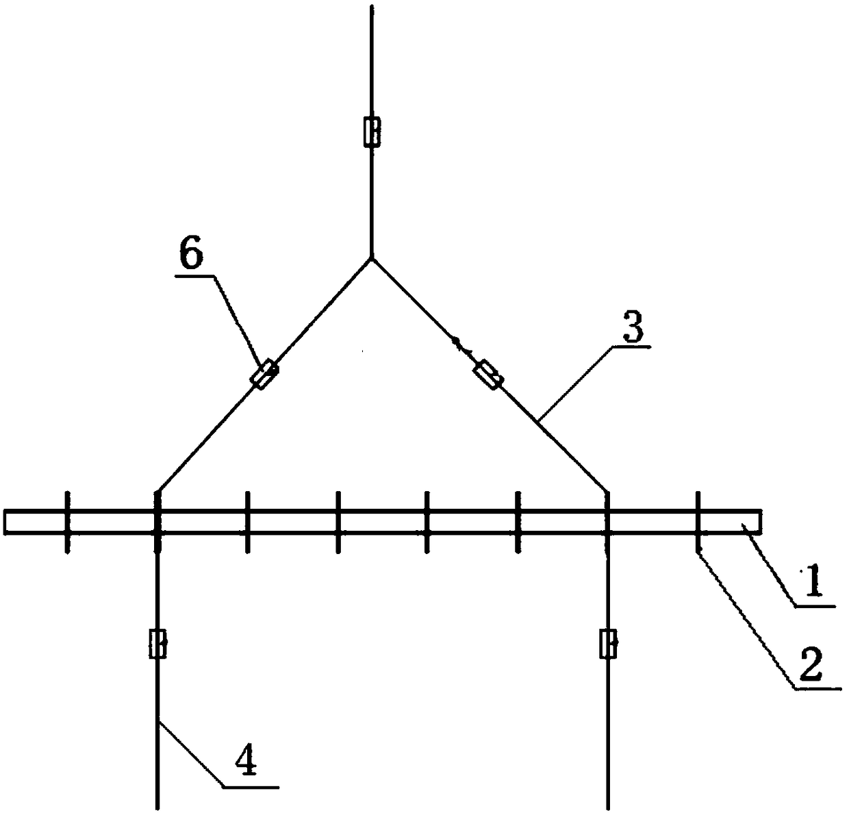
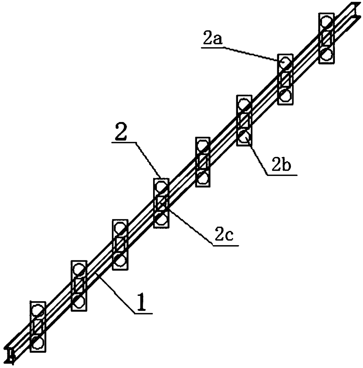
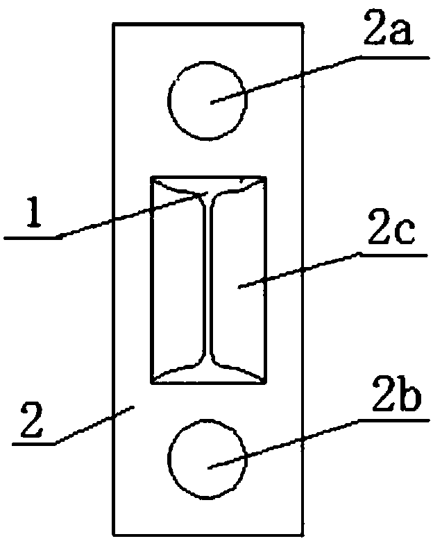
[0024] combine figure 1 with figure 2 As shown, a combined assembled hanger includes a beam 1 made of I-shaped steel, several hanging plates 2 equidistant and vertically fixed on the beam 1, several hanger wire ropes 3 and component connecting wire ropes 4. The upper and lower ends of the suspension plate 2 are provided with an upper hole 2a and a lower hole 2b respectively, the steel wire rope 3 of the spreader is connected in the symmetrical upper hole 2a, and the component connecting wire rope 4 is connected in the lower hole symmetrical within 2b. Preferably, the shape of...


PUM


Abstract

The invention relates to a combined split mounting type hoisting bracket. The combined split mounting type hoisting bracket comprises a cross beam, a plurality of hoisting plates which are verticallyfixedly connected at equal intervals to the cross beam, a plurality of hoisting tool steel wires and a plurality of component connecting steel wire ropes, wherein an upper quadrate hole and a lower quadrate hole are correspondingly formed in the upper end and the lower end of each hoisting plate; the hoisting tool steel wire ropes are connected into the upper square holes which are symmetrically distributed at the left and right; the component connecting steel wire ropes are connected into the lower quadrate holes which are symmetrically arranged at the left and right; high-precision displacement sensors are mounted on the hoisting tool steel wire ropes and the component connecting steel wire ropes. The invention also relates to a hoisting method of the abovementioned combined split mounting type hoisting bracket. According to the combined split mounting type hoisting bracket and the hoisting method, hoisting points can be freely selected based on the type and size of a precast component, so that the component can be stably and safely hoisted, and the shortage of frequent replacing of a traditional hoisting bracket can be avoided; the hoisting plates can be mounted by splicing andwelded at any time in the field, so that the generality is further improved; the deformation of the steel wire ropes can be monitored in real time through the high-precision displacement sensor, thusthe potential risk can be prevented, and as a result, the hoisting safety is ensured.

Description

technical field [0001] The invention relates to a combined assembled hanger and its hoisting method, in particular to a combined assembled hanger and its hoisting method for hoisting prefabricated components of different models, sizes and weights, and belongs to the technical field of building construction hoisting equipment. Background technique [0002] Prefabricated buildings refer to the fact that some or all of the components of the building are produced in the component prefabrication factory, and then transported to the construction site through corresponding transportation methods, and the components are assembled by reliable installation methods and installation machines to become functional buildings. way of building construction. Compared with on-site construction, prefabricated construction has the advantages of convenient construction, fast project progress, little impact on the surrounding environment, and easy guarantee of the quality of building components. ...

Claims


Application Information

Patent Timeline
Patent Type & Authority Applications(China)
IPC IPC(8): B66C1/12B66C13/08B66C13/16B66C15/06
CPCB66C1/12B66C13/08B66C13/16B66C15/065
Inventor 秦立标张延辉刘闪闪吴波士季方芮扬
Owner SHANGHAI NO 7 CONSTR
Why Eureka
Try Eureka