
Waste gas dust removal and adsorption treatment device

A technology for adsorption treatment and waste gas, which is applied in gas treatment, combined device, transportation and packaging, etc. It can solve the problems of wasting time, trouble, and troublesome replacement of activated carbon plates, and achieve the effect of increasing the contact area and improving the deacidification efficiency.

Active Publication Date: 2022-05-13
山东绿立冠环保科技有限公司
View PDF6 Cites 3 Cited by
  • Summary
  • Abstract
  • Description
  • Claims
  • Application Information

AI Technical Summary

Problems solved by technology

[0003] 1) During the exhaust gas filtration process, particles will continue to accumulate on the filter plate along with the filtration, greatly reducing the filtering effect. The conventional method is to frequently replace the filter plate, which is troublesome;
[0004] 2) The adsorption mechanism in the existing equipment needs to shut down the equipment when replacing the activated carbon adsorption plate. If the equipment is relatively large, the replacement of the activated carbon plate is more troublesome, which not only wastes time, but also reduces the efficiency of waste gas treatment;

Method used


Image

  • Waste gas dust removal and adsorption treatment device
  • Waste gas dust removal and adsorption treatment device
  • Waste gas dust removal and adsorption treatment device

Examples


Embodiment Construction

[0032] For the convenience of those skilled in the art to understand, the following in conjunction with the attached Figure 1-11 , to further specifically describe the technical solution of the present invention.

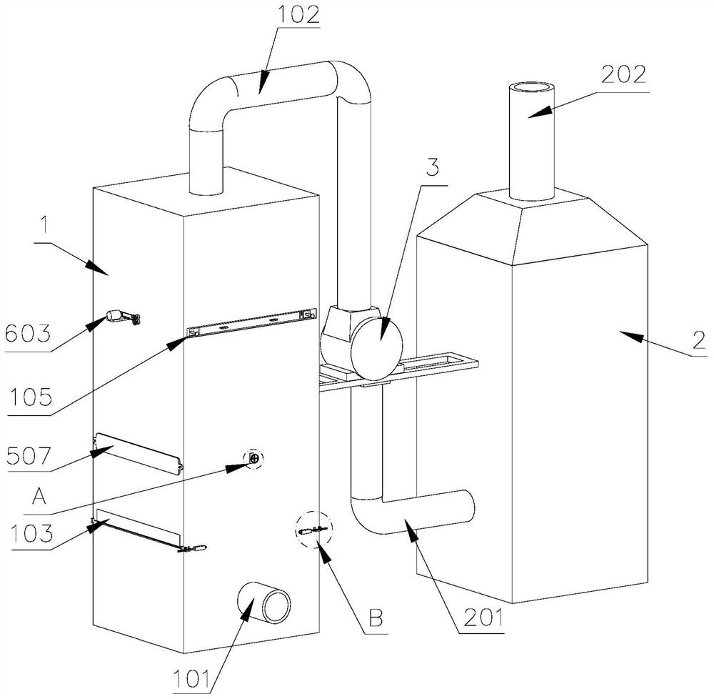
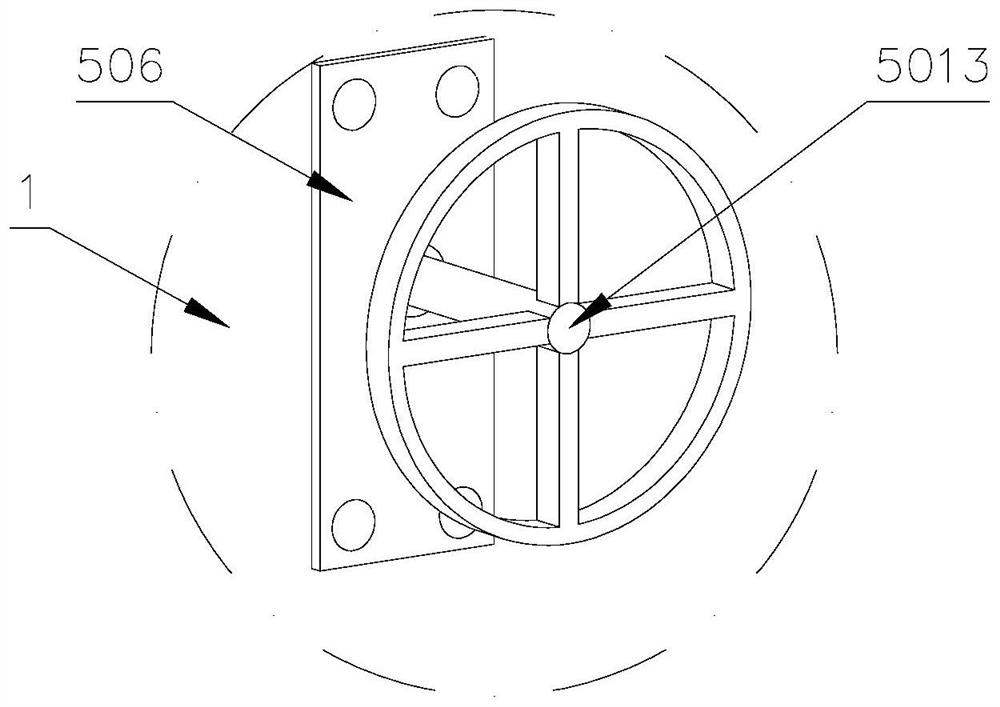
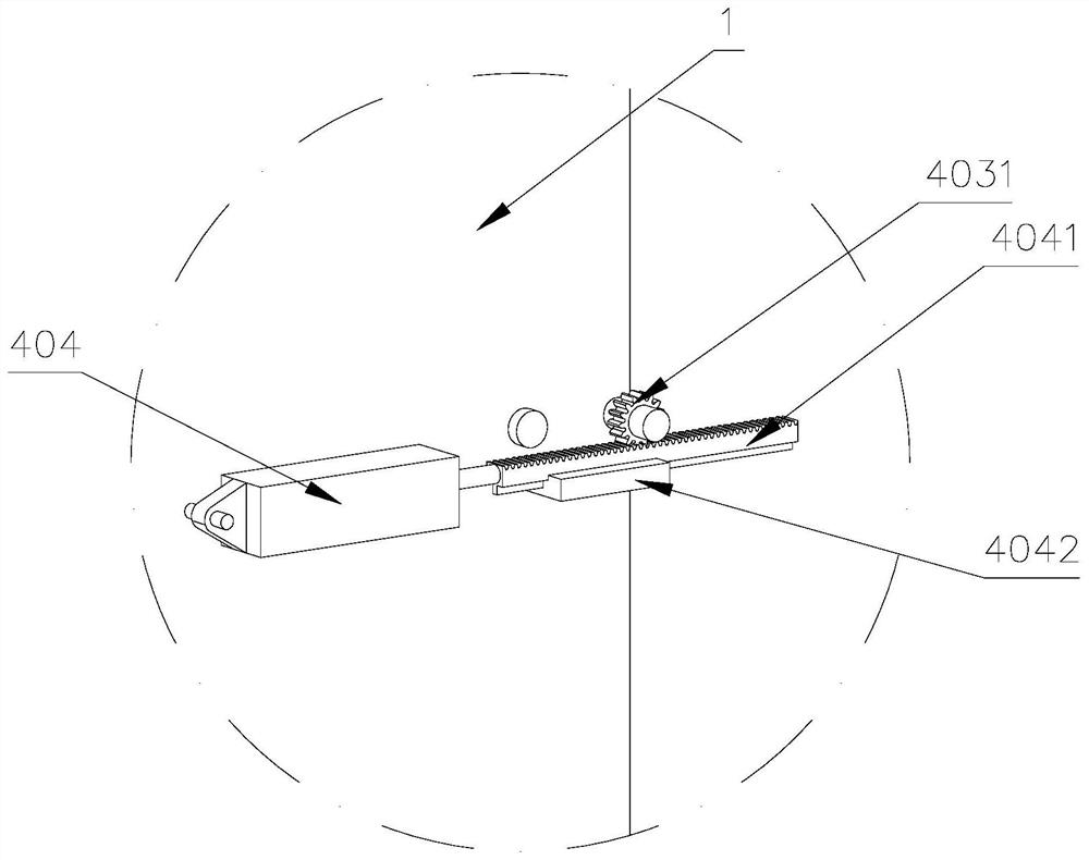
[0033]An exhaust gas dedusting adsorption treatment device, box body I1, box body II2, induced draft fan 3, adjustment mechanism 4, filter mechanism 5, adsorption mechanism 6, deacidification mechanism 7; box body I1 is set on the side of box body II2; induced draft fan 3 is set between the box body I1 and the box body II2 and is connected to each other through pipelines; the adjustment mechanism 4, the filter mechanism 5, and the adsorption mechanism 6 are set inside the box body I1, the adjustment mechanism 4 is set at the bottom of the box body I1, and the adsorption mechanism 6 Set on the top of the box I1, the filter mechanism 5 is set between the adjustment mechanism 4 and the adsorption mechanism 6; the deacidification mechanism 7 is set inside the box II; t...


PUM


Abstract

The invention discloses a waste gas dust removal and adsorption treatment device which comprises a box body I, a box body II, an induced draft fan, an adjusting mechanism, a filtering mechanism, an adsorption mechanism and a deacidification mechanism, the box body I is arranged on one side of the box body II; the induced draft fan is arranged between the box body I and the box body II and connected with each other through a pipeline; the adjusting mechanism, the filtering mechanism and the adsorption mechanism are arranged in the box body I, the adjusting mechanism is arranged at the bottom end of the box body I, the adsorption mechanism is arranged at the top end of the box body I, and the filtering mechanism is arranged between the adjusting mechanism and the adsorption mechanism; the deacidification mechanism is arranged in the box body II; an air inlet pipe I is arranged at the bottom of the box body I, an air outlet pipe I is arranged at the top and connected with an induced draft fan, a discharge port and a replacement port I are formed in one side of the box body I, and a replacement port II is formed in the other side of the box body I; an air inlet pipe II is arranged at the bottom of the box body II and connected with the induced draft fan; an air outlet pipe II is arranged at the top of the box body II. By using the filtering mechanism and the adsorption mechanism, the waste gas treatment efficiency can be improved.

Description

technical field [0001] The invention belongs to the technical field of waste gas treatment, and in particular relates to a waste gas dust removal adsorption treatment device. Background technique [0002] Industrial waste gas refers to all kinds of waste gas generated in industrial production, including ordinary dust waste gas, and acid-base waste gas generated in chemical production; industrial waste gas seriously pollutes the environment and affects human health; Some equipment generally filter the exhaust gas first, then perform adsorption treatment, and then neutralize the acid-base gas; the particulate matter in the exhaust gas will seriously affect the adsorption treatment of the exhaust gas; the existing problems are as follows: [0003] 1) During the exhaust gas filtration process, particles will continue to accumulate on the filter plate along with the filtration, greatly reducing the filtering effect. The conventional method is to frequently replace the filter plat...

Claims


Application Information

Patent Timeline
Patent Type & Authority Applications(China)
IPC IPC(8): B01D50/20B01D46/76B01D46/88B01D53/04B01D53/40B01D53/78
CPCB01D53/0407B01D53/0446B01D53/40B01D53/78B01D2253/102B01D2259/40084
Inventor 铁良张佃路
Owner 山东绿立冠环保科技有限公司
Learn More