A Balance Valve with Variable Pilot Ratio

A balance valve and variable technology, applied in the field of balance valves, can solve the problems of poor matching effect of hydraulic components, large energy loss of hydraulic system, high heat production of the system, etc., to reduce fuel consumption, reduce energy loss, open and close characteristics Good results

Active Publication Date: 2020-07-17
XUZHOU HEAVY MASCH CO LTD
View PDF7 Cites 0 Cited by
  • Summary
  • Abstract
  • Description
  • Claims
  • Application Information

AI Technical Summary

Problems solved by technology

The hydraulic system using this balance valve generally has a large energy loss, high heat production of the system, and the matching effect of the hydraulic components in the system is not good

Method used


Image

  • A Balance Valve with Variable Pilot Ratio
  • A Balance Valve with Variable Pilot Ratio
  • A Balance Valve with Variable Pilot Ratio

Examples


Embodiment 1

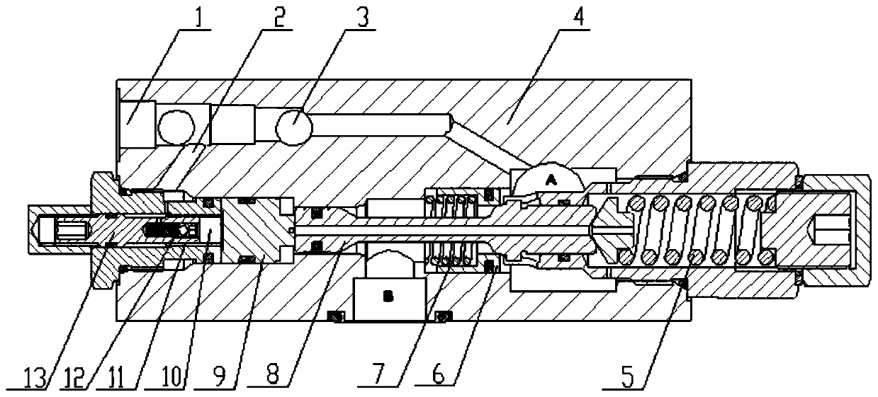
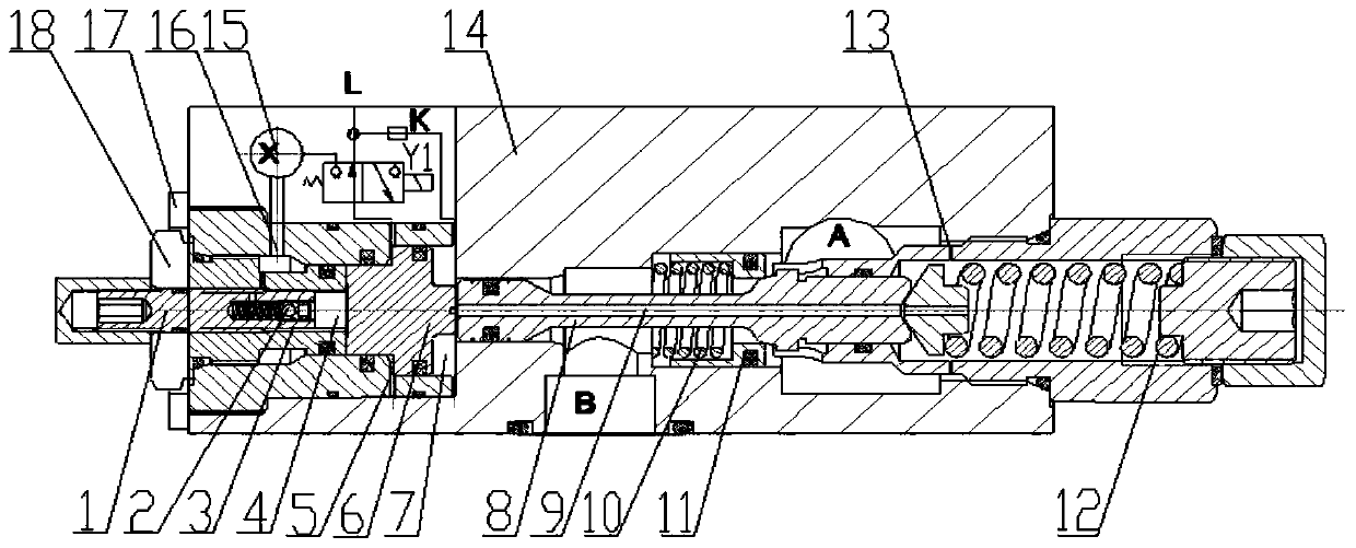
[0042] Such as image 3 and 4 As shown, a balance valve with variable pilot ratio includes a valve body 14, a valve core 8, an adjusting screw 1, a first one-way valve 11, a second one-way valve 2, a first spring 10, a second spring, a reset Spring 12, valve sleeve 18, valve seat, end cover 17 and control piston 6.

[0043] The valve body 14 has a control oil port 15, an oil port A, an oil port B, an oil drain port L and a through cavity. Both the valve core 8 and the control piston 6 are slidably installed in the cavity, and the control piston 6 has a first action surface 23 and a second action surface 24 located at two ends. One end of the spool 8 abuts against the second acting surface 24 to transmit the control force, and the other end is slidably installed in the valve seat and forms an elastic connection with the valve seat through the return spring 12, and the moving spool 8 can control the first one-way valve 11 The opening to control the opening of the balance valv...

Embodiment 2

[0051] Such as Figure 5 As shown, the difference from Embodiment 1 is that in this embodiment, the control piston 6 has three annular bosses 25 formed in an axially stepped arrangement, and the end cover has three formed in an axially stepped arrangement so as to be compatible with the corresponding The annular boss 25 forms the annular groove 19 for sliding sealing, so the number of second chambers 5 constructed in this embodiment is three. Each second chamber 5 is connected with the control valve through a second oil passage 20 . The pilot ratio is increased by inputting control oil into the three second chambers 5 .

Embodiment 3

[0053] The difference from the second embodiment is that, in this embodiment, the number of control valves is also three, and the oil outlets are respectively connected with a second oil passage 20 to realize sequential control.


PUM


Abstract

The invention discloses a balance valve with the variable pilot ratio. A valve body is provided with a control oil port, and a control piston is provided with a first acting surface and a second acting surface which are located at the two ends. A valve sleeve is provided with a first containing cavity. The first containing cavity is close to the first acting surface. One end of a valve core abutsagainst the second acting surface. An end cap and the control piston are in sliding sealing connection. The control piston is provided with at least one annular boss, and the end surface of the side,close to the first containing cavity, of each annular boss is a first annular acting surface. The end cap is provided with at least one annular groove in sliding sealing fit with the corresponding annular boss and at least one oil passageway communicating with the corresponding annular groove. The end surface of the side, close to the first containing cavity, of each annular groove is a second annular acting surface. A second containing cavity is formed between each first annular acting surface and the corresponding second annular acting surface. The balance valve has the beneficial effects that the low pilot ratio can be adopted in a working condition requiring high system stability and the high pilot ratio can be adopted in a steady state working condition, so that the system energy consumption is lowered.

Description

technical field [0001] The invention belongs to the technical field of engineering machinery, and in particular relates to a balance valve with variable pilot ratio. Background technique [0002] With the development of society and the continuous improvement of mobile crane users' requirements for equipment use, the focus of research and development of mobile cranes has shifted from meeting the basic requirements of users to the direction of intelligence, high reliability, low energy consumption and human-computer interaction comfort. High-performance mobile cranes also have higher requirements on hydraulic components. In the telescopic, luffing, and hoisting systems of mobile truck cranes, in order to ensure the safety of the hydraulic system, hydraulic balance valves with locking functions are installed on the actuators, which are mainly used to prevent the load position caused by internal leakage of the system. Changes and hydraulic pipeline damage caused safety accident...

Claims


Application Information

Patent Timeline
Patent Type & Authority Patents(China)
IPC IPC(8): F15B20/00F15B13/02
CPCF15B13/023F15B20/00
Inventor 王建成东权张鑫向小强陈龙吕传祥
Owner XUZHOU HEAVY MASCH CO LTD
Why Eureka
Try Eureka