Photographing optical lens system, image capturing unit and electronic device
An optical lens and image capture technology, applied in the field of image capture optical lens system
- Summary
- Abstract
- Description
- Claims
- Application Information
AI Technical Summary
Problems solved by technology
Method used
Image
Examples
no. 1 example
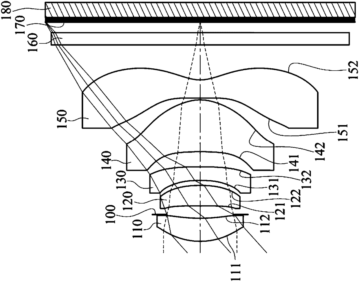
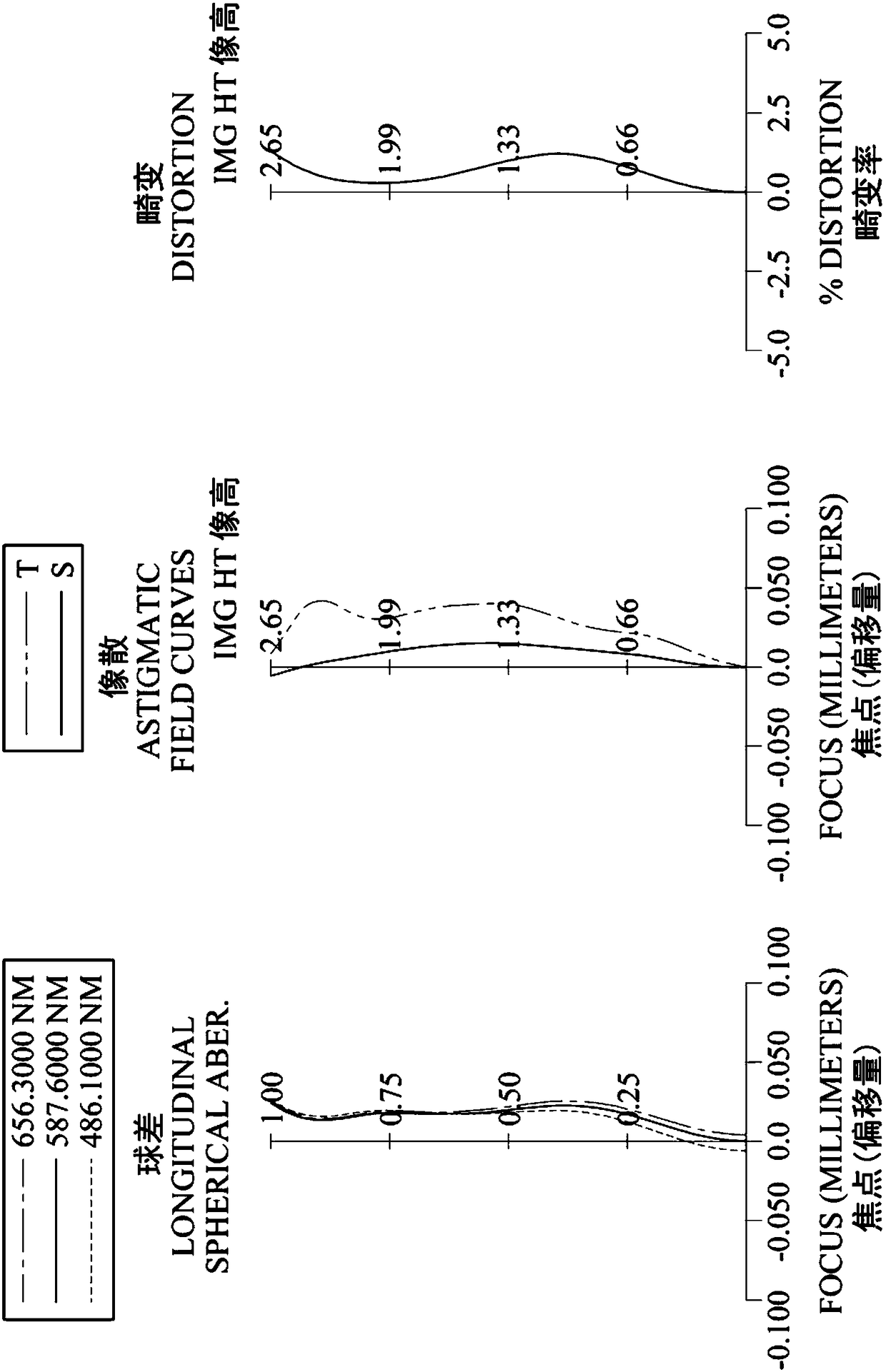
[0132] Please refer to Figure 1 to Figure 2 ,in figure 1 A schematic diagram of an imaging device according to a first embodiment of the present invention is shown, figure 2 From left to right are the spherical aberration, astigmatism and distortion curves of the first embodiment. Depend on figure 1 It can be seen that the image capturing device includes an image capturing optical lens system (not otherwise labeled) and an electronic photosensitive element 180 . The image capture optical lens system includes a first lens 110, an aperture 100, a second lens 120, a third lens 130, a fourth lens 140, a fifth lens 150, and an infrared filter element ( IR-cut Filter) 160 and imaging surface 170. Wherein, the electronic photosensitive element 180 is disposed on the imaging surface 170 . The total number of lenses (110-150) in the image capturing optical lens system is five.
[0133] The first lens 110 has positive refractive power and is made of plastic material. The object-...
no. 2 example
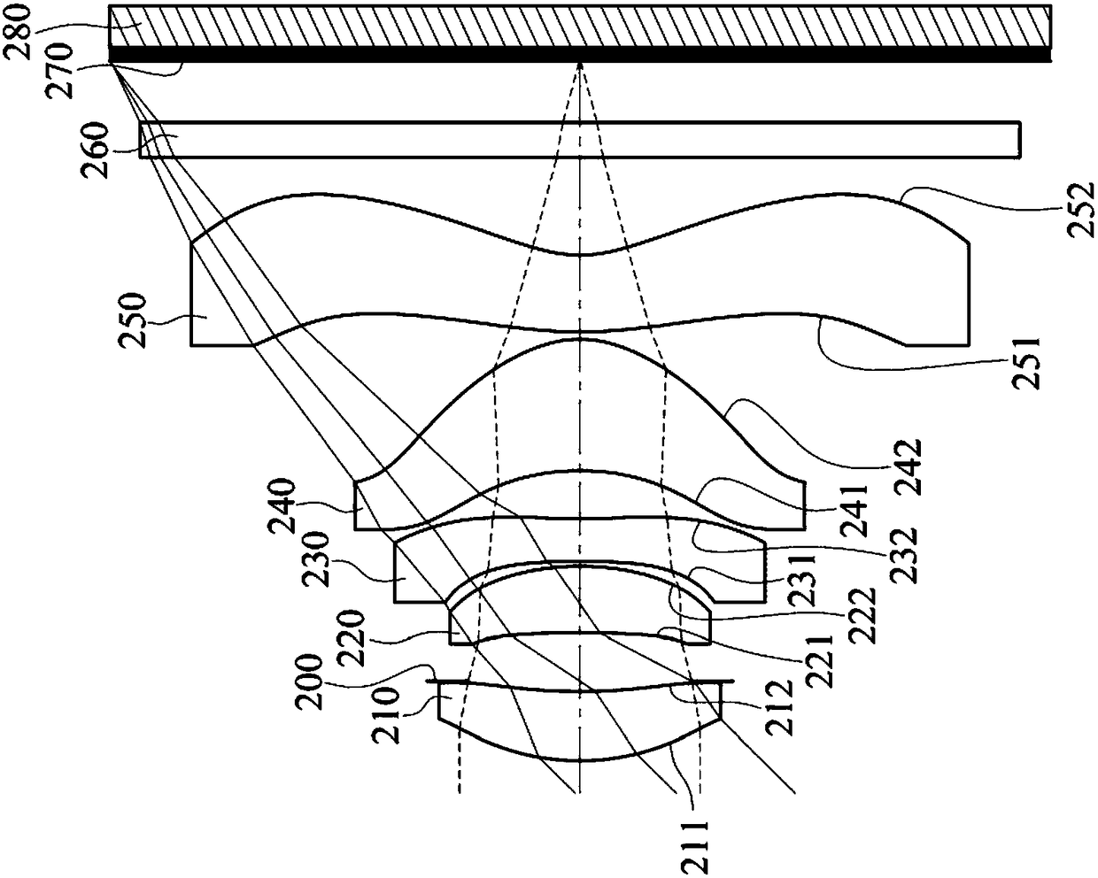
[0165] Please refer to Figure 3 to Figure 4 ,in image 3 A schematic diagram of an imaging device according to a second embodiment of the present invention is shown, Figure 4 From left to right are the spherical aberration, astigmatism and distortion curves of the second embodiment. Depend on image 3 It can be seen that the image capturing device includes an image capturing optical lens system (not otherwise labeled) and an electronic photosensitive element 280 . The image capture optical lens system sequentially includes a first lens 210 , an aperture 200 , a second lens 220 , a third lens 230 , a fourth lens 240 , a fifth lens 250 , and an infrared filter element 260 from the object side to the image side. with imaging surface 270 . Wherein, the electronic photosensitive element 280 is disposed on the imaging surface 270 . The total number of lenses (210-250) in the image capturing optical lens system is five.
[0166] The first lens 210 has positive refractive powe...
no. 3 example
[0180] Please refer to Figure 5 and Figure 6 ,in Figure 5 A schematic diagram of an imaging device according to a third embodiment of the present invention is shown, Figure 6 From left to right are the spherical aberration, astigmatism and distortion curves of the third embodiment. Depend on Figure 5 It can be seen that the image capturing device includes an image capturing optical lens system (not otherwise labeled) and an electronic photosensitive element 380 . The image capture optical lens system sequentially includes a first lens 310 , an aperture 300 , a second lens 320 , a third lens 330 , a fourth lens 340 , a fifth lens 350 , and an infrared filter element 360 from the object side to the image side. with imaging surface 370 . Wherein, the electronic photosensitive element 380 is disposed on the imaging surface 370 . The total number of lenses (310-350) in the image capturing optical lens system is five.
[0181] The first lens 310 has positive refractive p...
PUM
 Abstract
Description
Claims
Application Information
 - R&D
- Intellectual Property
- Life Sciences
- Materials
- Tech Scout
- Unparalleled Data Quality
- Higher Quality Content
- 60% Fewer Hallucinations
Browse by: Latest US Patents, China's latest patents, Technical Efficacy Thesaurus, Application Domain, Technology Topic, Popular Technical Reports.
© 2025 PatSnap. All rights reserved.Legal|Privacy policy|Modern Slavery Act Transparency Statement|Sitemap|About US| Contact US: help@patsnap.com


