
Optical system, imaging device and electronic device for photography

An optical system and optical axis technology, applied in optics, optical components, instruments, etc., can solve the problems of unsatisfactory imaging quality, difficulty in suppressing the angle of light, difficulty in forming and suitable sensitivity, etc., so as to improve imaging quality , Improve convenience and reduce strength

Active Publication Date: 2019-01-29
LARGAN PRECISION
View PDF9 Cites 0 Cited by
  • Summary
  • Abstract
  • Description
  • Claims
  • Application Information

AI Technical Summary

Problems solved by technology

Although this structural configuration helps to reduce the back focal length, it is not easy to suppress the angle of light incident on the photosensitive element
In addition, in the telescopic optical system with a small viewing angle, the existing structural configuration also has the disadvantage that it is not easy to achieve a balance between easy molding and suitable sensitivity
[0004] To sum up, although the existing four-chip optical system has the advantage of miniaturization, the imaging quality is still not ideal. Therefore, there is an urgent need in the field for a photographic optical system that meets the needs of miniaturization and high imaging quality.

Method used


Image

  • Optical system, imaging device and electronic device for photography
  • Optical system, imaging device and electronic device for photography
  • Optical system, imaging device and electronic device for photography

Examples


no. 1 example 》

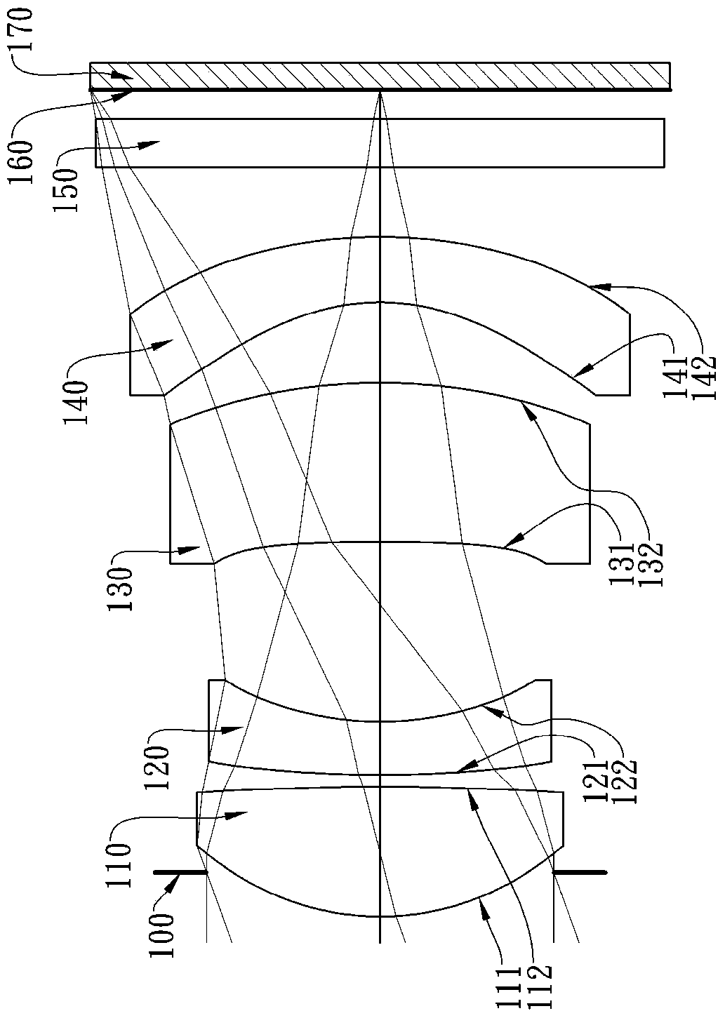
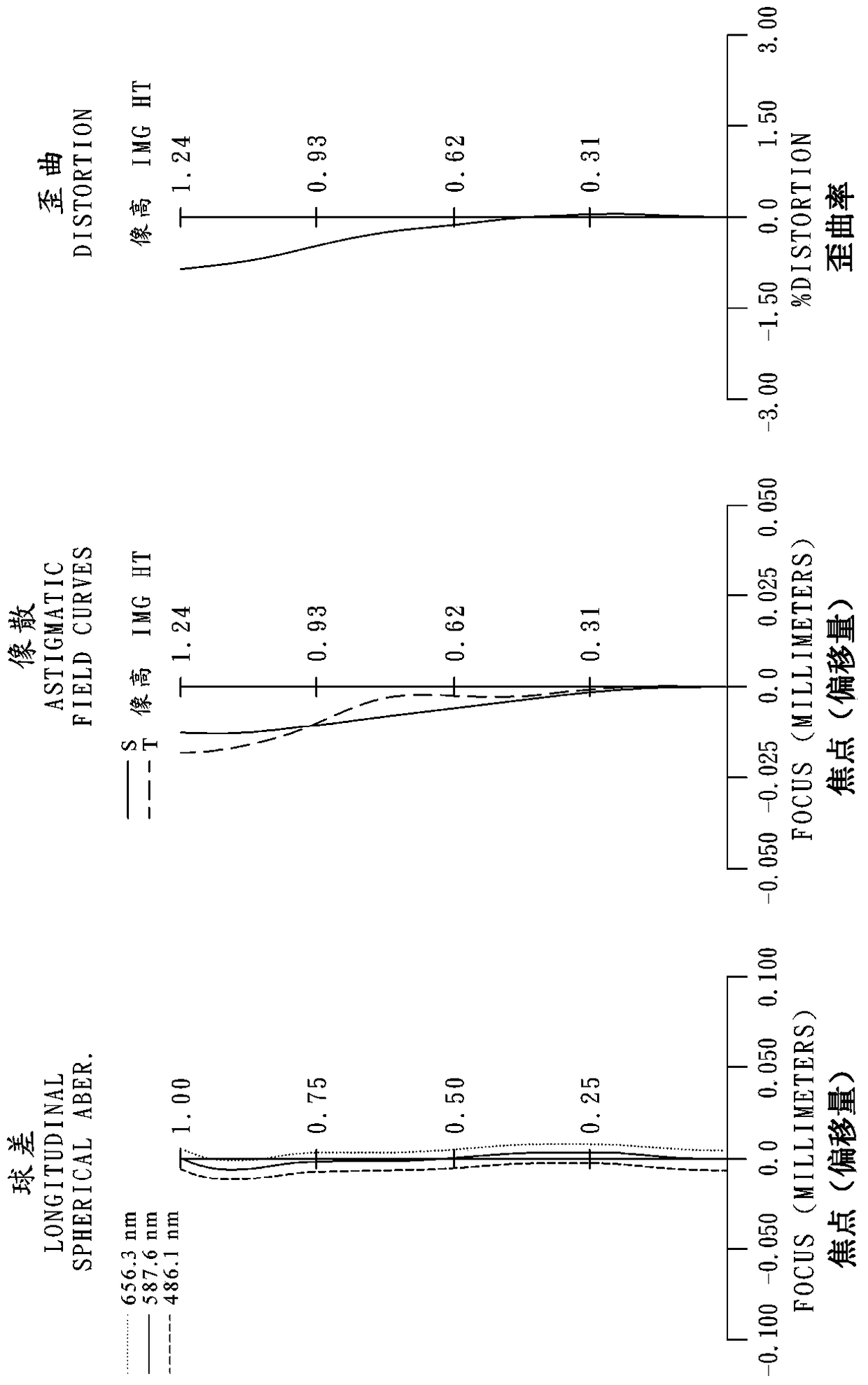
[0089] Please refer to the first embodiment of the present invention Figure 1A , for the aberration curve of the first embodiment, please refer to Figure 1B . The imaging device of the first embodiment includes a photographic optical system (not otherwise labeled) and an electronic photosensitive element (170). The photographic optical system mainly consists of four first lenses 110 and second lenses 120 with refractive power. , the third lens 130, and the fourth lens 140, which sequentially include from the object side to the image side:

[0090] A first lens 110 with positive refractive power is made of plastic, its object side 111 is convex at the near optical axis, its image side 112 is convex at the near optical axis, and its object side 111 and image side 112 are both is aspheric;

[0091] A second lens 120 with negative refractive power is made of plastic, its object side 121 is convex at the near optical axis, its image side 122 is concave at the near optical axis,...

no. 2 example 》

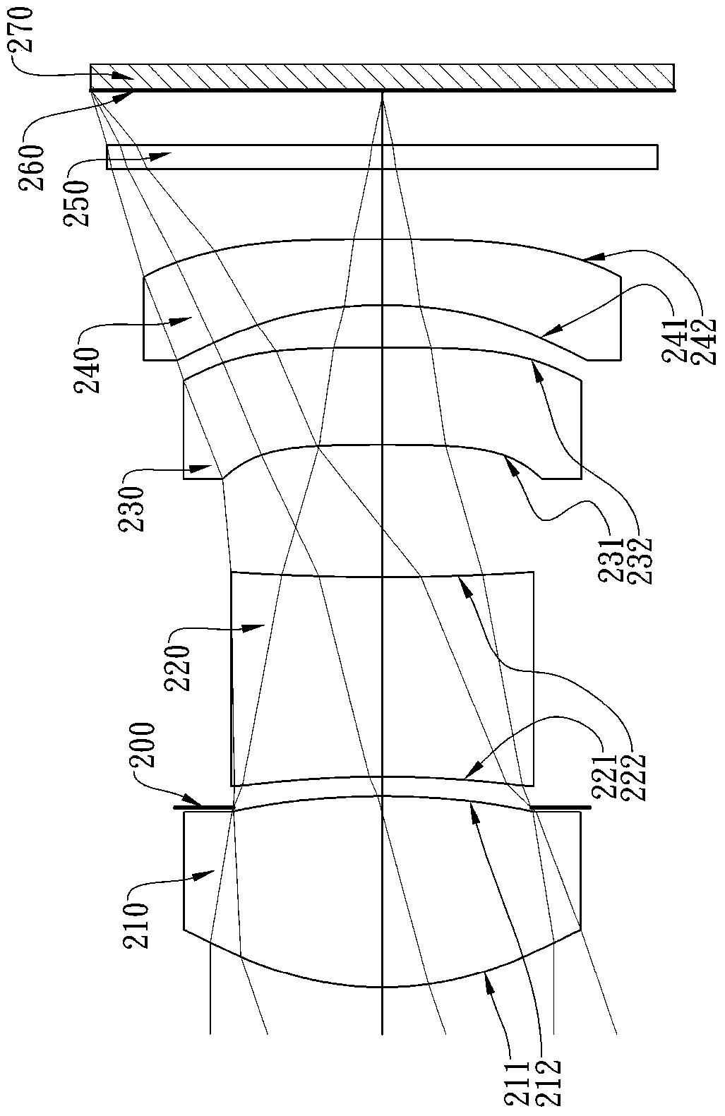
[0122] Please refer to the second embodiment of the present invention Figure 2A , for the aberration curve of the second embodiment, please refer to Figure 2B . The imaging device of the second embodiment includes a photographic optical system (not otherwise labeled) and an electronic photosensitive element 270. The photographic optical system is mainly composed of four first lenses 210, second lenses 220, and four with refractive power. The three lenses 230 and the fourth lens 240 consist of the following sequentially from the object side to the image side:

[0123] A first lens 210 with positive refractive power is made of plastic, its object side 211 is convex at the near optical axis, its image side 212 is convex at the near optical axis, and its object side 211 and image side 212 are both is aspheric;

[0124] A second lens 220 with negative refractive power is made of plastic, its object side 221 is concave at the near optical axis, its image side 222 is concave at ...

no. 3 example 》

[0135] Please refer to the third embodiment of the present invention Figure 3A , for the aberration curve of the third embodiment, please refer to Figure 3B . The imaging device of the third embodiment includes a photographic optical system (not otherwise labeled) and an electronic photosensitive element 370. The photographic optical system is mainly composed of four first lenses 310, second lenses 320, and four with refractive power. The three lenses 330 and the fourth lens 340 consist of the following sequentially from the object side to the image side:

[0136] A first lens 310 with positive refractive power is made of plastic, its object side 311 is convex at the near optical axis, its image side 312 is convex at the near optical axis, and its object side 311 and image side 312 are both is aspheric;

[0137] A second lens 320 with negative refractive power is made of plastic, its object side 321 is convex at the near optical axis, its image side 322 is concave at the ...


PUM


Abstract

The invention provides a photographing optical system, an image capturing device, and an electronic device. From the object space to the image space, the photographing optical system sequentially comprises a first lens which has positive refraction power, wherein the object space surface is a convex surface at a near optical axis; a second lens with the negative refraction power; a third lens, wherein the object space surface is a concave surface at the near optical axis, and the object space surface and the image space surface are aspheric surfaces; a fourth lens which has negative refraction power, wherein the object space surface is a concave surface at the near optical axis, the image space surface is a convex surface at the near optical axis, and the object space surface and the image space surface are aspheric surfaces. The front system configuration facilitates the obtaining of the balance between forming easiness and the proper sensitivity, and the obtaining of a better telescoping capability. In addition, the direction change of light can be slowed down after the light enters the system, thereby facilitating the reduction of the intensity of stray light, and improving the imaging quality.

Description

technical field [0001] The present invention relates to a photographic optical system and an image capturing device, in particular to a photographic optical system and an image capturing device applicable to electronic devices. Background technique [0002] With the gradual thinning of personal electronic products, the internal components of electronic products are required to have a smaller size. Under the market trend, the size of the photographic optical system must be miniaturized. In addition to the requirement of miniaturization, the pixel area of ​​the photosensitive element is reduced due to the advancement of semiconductor process technology, and the imaging lens is gradually developing into the field of high pixel. At the same time, the rise of electronic devices such as smartphones and tablet computers has also increased the demand for high-quality optical systems for miniature photography. [0003] The existing four-piece optical system is usually configured wi...

Claims


Application Information

Patent Timeline
Patent Type & Authority Patents(China)
IPC IPC(8): G02B13/18G02B13/00
Inventor 谢东益陈纬彧
Owner LARGAN PRECISION
Learn More