An electrowetting display and its manufacturing method

An electrowetting display and manufacturing method technology, applied in the directions of instruments, optical components, optics, etc., can solve the problems of high parallelism requirements, large equipment footprint, unsuitable for flexible display devices, etc., to avoid the phenomenon of overturning the wall , The filling uniformity is good, and the effect of ensuring the distance between boxes

Active Publication Date: 2020-11-03
ACADEMY OF SHENZHEN GUOHUA OPTOELECTRONICS +2
View PDF2 Cites 0 Cited by
  • Summary
  • Abstract
  • Description
  • Claims
  • Application Information

AI Technical Summary

Problems solved by technology

However, this method is difficult to fill large-area displays, and requires high parallelism between the filling head and the substrate. The filling method is slow, the equipment occupies a large area, and there is no way to control the filling thickness of the ink layer. The filled device needs spacers to control device gap
In addition, the University of Cincinnati and Liquivista proposed a filling method using the rise and fall of the electrolyte liquid level. Although this method can avoid complicated equipment and operating procedures, the filling uniformity is not good, and it is not suitable for the filling of large-area displays, let alone Suitable for filling of flexible display devices

Method used


Image

  • An electrowetting display and its manufacturing method
  • An electrowetting display and its manufacturing method
  • An electrowetting display and its manufacturing method

Examples


Embodiment 1

[0031] The invention provides a method for manufacturing an electrowetting display, comprising the following steps:

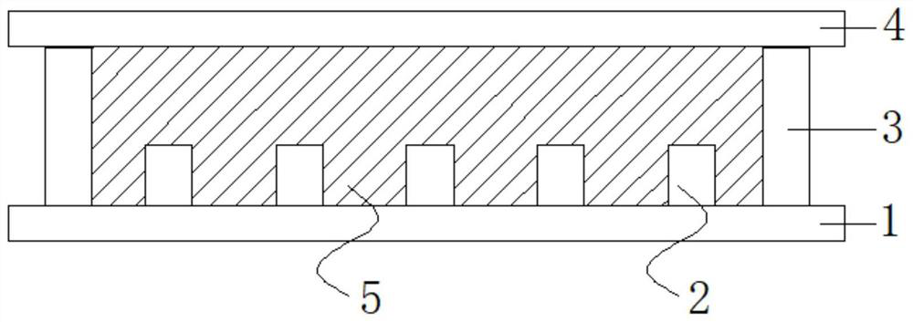
[0032] Take off the substrate, the lower substrate includes a substrate, a conductive layer and an insulating layer arranged in sequence, and the substrate can be a rigid substrate such as glass, or a flexible substrate such as a PET plate, a PEN plate, a PI plate; the conductive layer can be It is an ITO conductive layer or a PI conductive layer; the insulating layer can be a layer of hydrophobic insulating layer material, or a composite layer obtained by adding a layer of hydrophobic coating on the surface of the insulating material, such as silicon dioxide, silicon nitride, organic Spin-coat hydrophobic layer materials on the surface of insulating materials such as insulating materials. The hydrophobic layer materials mainly include DuPont’s AF fluororesin series (such as AF1600), CYTOP fluororesin from Japan’s Asahi Whistle, and Solvay’s Hyflon fluororesin. ...

Embodiment 2

[0039] The invention provides a method for manufacturing an electrowetting display, comprising the following steps:

[0040] Take the substrate, the substrate material of the lower substrate is a flexible substrate PET board, and then prepare a pixel wall on the lower substrate, the pixel wall encloses a pixel grid, the length of the bottom surface of the pixel grid: width = 1.5: 1, the The height of the pixel grid: the length of the pixel grid=2:1. In the present invention, the shape of the bottom surface of the pixel grid can be a rectangle, preferably the length of the bottom surface: width=(1.5-2):1.

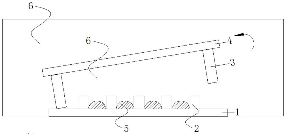
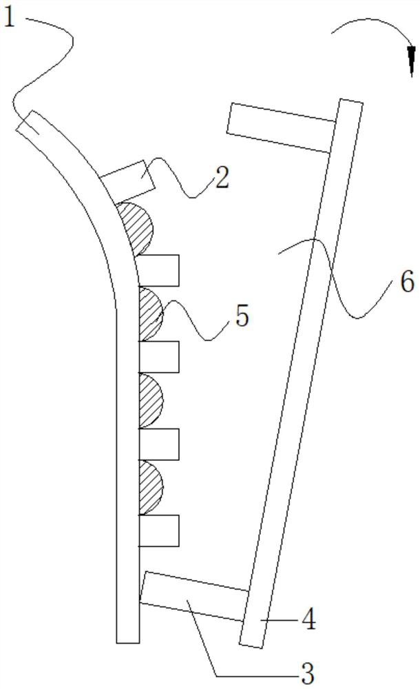
[0041] Preparation of filling plate: take a hydrophilic glass substrate, use acrylic ultraviolet curing glue to stick a PET frame on the hydrophilic glass substrate, the area of ​​the PET frame is larger than the area surrounded by the pixel wall, and the thickness of the PET frame is 100 μm.

[0042] Fill the pixel grid with ink with a concentration of 30%, and cover the f...


PUM

PropertyMeasurementUnit
thicknessaaaaaaaaaa
lengthaaaaaaaaaa
thicknessaaaaaaaaaa

Abstract

The invention discloses an electric moistening display and a producing method thereof. The height of a prepared pixel grid is controlled to be greater than or equal to the length of the pixel grid, based on the principle that the capillary force of the pixel grid having a relatively large height-length ratio is greater than the adhesion force of ink to the surface of the pixel grid, the thicknessof the ink inside the pixel grid is controlled, then the thickness of the ink is less than the pixel grid, and the phenomenon that the ink overflows in the on / off process can be avoided. The producingmethod disclosed by the invention is simple in process, rapid in filling speed, good in filling uniformity and applicable to filling of large-area displays and flexible display devices.

Description

technical field [0001] The invention relates to the field of displays, in particular to an electrowetting display and a manufacturing method thereof. Background technique [0002] In 2003, Rob and others invented the display technology based on the principle of electrowetting, officially pushing the electrowetting display into the display industry. At the same time, the University of Cincinnati was also a pioneer in the study of electrowetting displays, and made great achievements in fluorescent and transmissive optical devices. Electrowetting display has the advantages of total reflection, full color and can display dynamic video (response speed is less than 10ms). One of the challenges surrounding electrowetting display devices is their special assembly process, including ink filling and device packaging techniques. At present, in the prior art, filling equipment is usually used to fill ink. For example, wo2009 / 065909A1 and wo2008 / 125644A1 describe a kind of equipment fo...

Claims


Application Information

Patent Timeline
Patent Type & Authority Patents(China)
IPC IPC(8): G02B26/00
CPCG02B26/005
Inventor 周国富郭媛媛
Owner ACADEMY OF SHENZHEN GUOHUA OPTOELECTRONICS
Why Eureka
Try Eureka