

Process generation method and terminal equipment
A process and flow chart technology, applied in the field of communication, can solve the problem of heavy development workload of process generation methods, and achieve the effect of reducing the workload of process development
- Summary
- Abstract
- Description
- Claims
- Application Information
AI Technical Summary
Problems solved by technology
Method used
Image

Examples
Embodiment 1
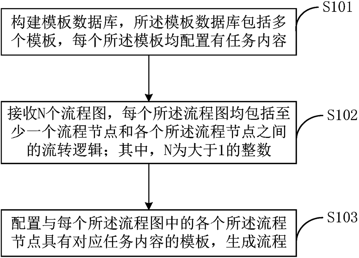
[0042] Please refer to figure 1 , the process generation methods include:
[0043] Step S101, constructing a template database, the template database includes a plurality of templates, each of which is configured with task content.
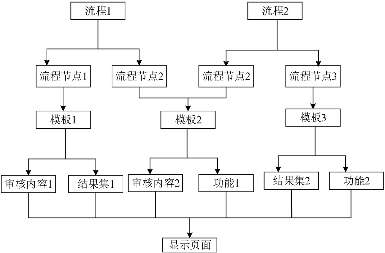
[0044] In the embodiment of the present invention, the task content refers to the task to be performed by the process node, including but not limited to the content to be displayed, the result set, the function to be realized, and the field to be reviewed. The user configures the task content of each process node in different templates. Since the same process node has the same task content, only one template needs to be configured. For example, as figure 2 As shown, process 1 includes process node 1 and process node 2, and process 2 includes process node 2 and process node 3. Since process 1 and process 2 have the same process node 2, only template 1 corresponding to process node 1 needs to be configured , template 2 corresponding to process n...
Embodiment 2
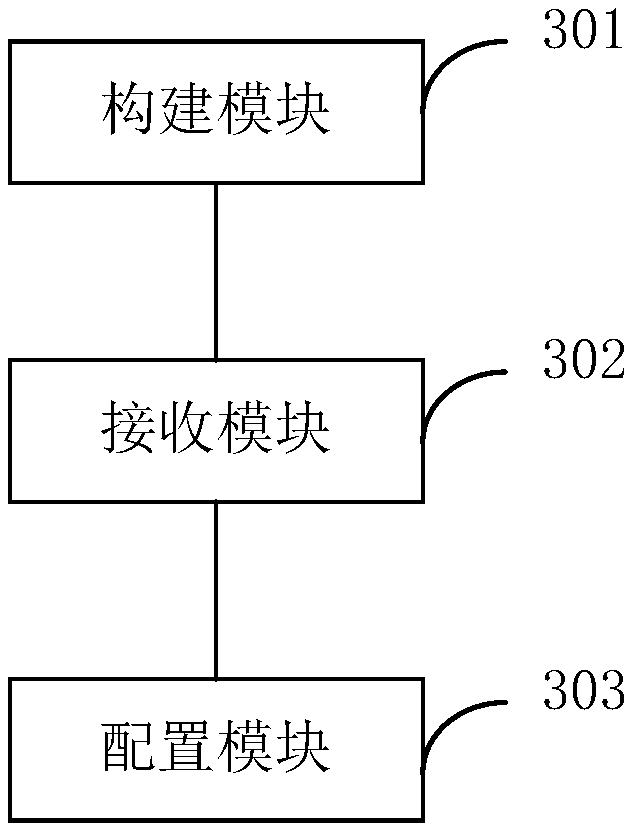
[0069] Please refer to image 3 , the process generation device includes a construction module 301 , a receiving module 302 and a configuration module 303 .
[0070] The construction module 301 is configured to construct a template database, the template database includes a plurality of templates, and each template is configured with corresponding task content.
[0071] The receiving module 302 is configured to receive flow N flow charts, each of which includes at least one process node and flow logic between each process node; wherein, N is an integer greater than 1.
[0072] The configuration module 303 is configured to configure a template having task content corresponding to each of the process nodes in each of the flowcharts to generate a process.
[0073] Optionally, the template includes first identification information, and the process node includes second identification information;
[0074] The configuration module 303 is configured to configure, according to the f...
Embodiment 3
[0086] Figure 4 It is a schematic diagram of a flow generation terminal device provided by an embodiment of the present invention. like Figure 4 As shown, the flow generation terminal device 4 of this embodiment includes: a processor 40 , a memory 41 and a computer program 42 stored in the memory 41 and operable on the processor 40 . When the processor 40 executes the computer program 42, it implements the steps in the above-mentioned embodiments of the process generation method, for example figure 1 Steps 101 to 104 are shown. Alternatively, when the processor 40 executes the computer program 42, it realizes the functions of the modules / units in the above-mentioned device embodiments, for example image 3 The functions of modules 301 to 303 are shown.
[0087] Exemplarily, the computer program 42 may be divided into one or more modules / units, and the one or more modules / units are stored in the memory 41 and executed by the processor 40 to complete the this invention. ...
PUM
 Abstract
Description
Claims
Application Information