Improved new energy automobile charging equipment

A technology for new energy vehicles and charging equipment, which is applied to electric vehicle charging technology, charging stations, electric vehicles, etc. It can solve the problems of not installing a locking device, affecting the use of charging, and falling off of the charging gun, so as to achieve simple and convenient control and increase The effect of using efficiency and increasing the service life

Inactive Publication Date: 2018-06-29
广州一恒科技有限公司
View PDF4 Cites 2 Cited by
  • Summary
  • Abstract
  • Description
  • Claims
  • Application Information

AI Technical Summary

Problems solved by technology

[0002] With the country's vigorous promotion of energy saving and environmental protection, the use of new energy vehicles is increasing. Before using new energy vehicles, the batteries in new energy vehicles need to be charged. Traditionally, the charging guns connected to new energy vehicles are directly charged. Insert into the charging part, there is no locking device between the charging gun and the charging part, so when accidentally touching the wire connected to the new energy vehicle, the charging gun will accidentally fall off from the charging part, resulting in interruption of charging and affecting charging use, and the insertion cavity of the traditional charging part is directly charged, so it is easy to cause an electric shock accident when the charging gun is plugged into the charging part.

Method used


Image

  • Improved new energy automobile charging equipment
  • Improved new energy automobile charging equipment
  • Improved new energy automobile charging equipment

Examples


Embodiment Construction

[0022] The preferred embodiments of the present invention will be described in detail below in conjunction with the accompanying drawings, so that the advantages and features of the present invention can be more easily understood by those skilled in the art, so as to define the protection scope of the present invention more clearly.

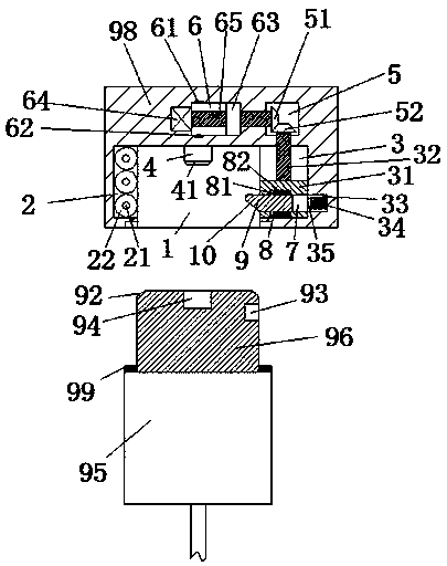
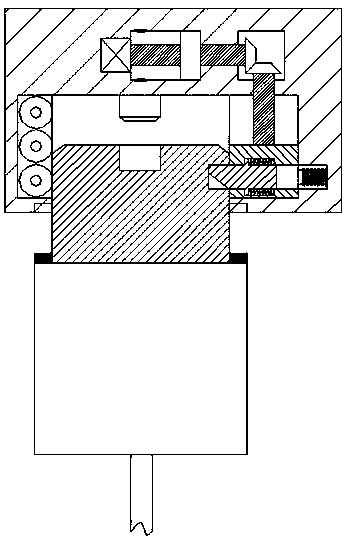
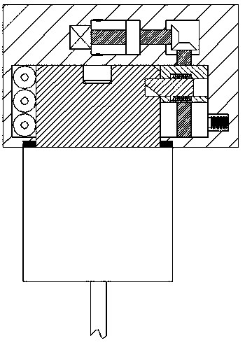
[0023] refer to Figure 1-4 The shown improved new energy vehicle charging equipment includes a charging pile body 100, a charging part 98 arranged on the upper left side of the charging pile body 100, and a charging gun for cooperating with the charging part 98. The charging part 98 includes an insertion cavity 1 with the mouth downwardly disposed. The left and right end walls of the insertion cavity 1 are respectively provided with a first sliding groove 2 and a second sliding groove 3 correspondingly. A power receiving slot 6 is provided above the insertion chamber 1, a receiving slot 5 is provided above the second sliding slot 3 in the chargi...


PUM


Abstract

The invention discloses improved new energy automobile charging equipment, which comprises a charging pile body, a charging part arranged at the upper left part of the charging pile body, and a charging gun used for being connected with the charging part in a matched mode. The charging part comprises an inserting cavity with an opening facing downwards. A first sliding groove and a second slidinggroove are symmetrically formed in the left and right end walls of the inserting cavity separately. A power connecting groove is formed in a position, above the inserting cavity, in the charging part.An accommodating groove is formed in a position, above the second sliding groove, in the charging part. The improved new energy automobile charging equipment is simple in overall structure, is safe and reliable in operation, guarantees the life safety of users, is simple and convenient in running operations of the whole equipment, can realize the locking and fixing of the charging gun, and prolongs the service life.

Description

technical field [0001] The invention relates to the technical field of new energy vehicles, in particular to an improved charging device for new energy vehicles. Background technique [0002] With the country's vigorous promotion of energy saving and environmental protection, the use of new energy vehicles is increasing. Before using new energy vehicles, the batteries in new energy vehicles need to be charged. Traditionally, the charging guns connected to new energy vehicles are directly charged. Insert into the charging part, there is no locking device between the charging gun and the charging part, so when accidentally touching the wire connected to the new energy vehicle, the charging gun will accidentally fall off from the charging part, resulting in interruption of charging and affecting charging Use, and the insertion cavity of the traditional charging part is all directly charged, so it is easy to cause electric shock accidents when the charging gun is plugged into th...

Claims


Application Information

Patent Timeline
Patent Type & Authority Applications(China)
IPC IPC(8): H01R13/502H01R13/627H01R13/629H01R13/639H01R13/70B60L11/18
CPCB60L53/16B60L53/31H01R13/502H01R13/6275H01R13/629H01R13/639H01R13/701H01R2201/26Y02T10/70Y02T10/7072Y02T90/12Y02T90/14
Inventor 潘燕
Owner 广州一恒科技有限公司
Why Eureka
Try Eureka