Improved water cup

An improved water cup technology, which is applied to water boiling appliances, electrical components, coupling devices, etc., can solve the problems of cup body burning, exposed power transmission grooves, and power transmission terminals detached, and achieves simple and convenient operation, safe and stable power supply, Good power supply stability

Inactive Publication Date: 2018-06-29
玉明福
View PDF3 Cites 0 Cited by
  • Summary
  • Abstract
  • Description
  • Claims
  • Application Information

AI Technical Summary

Problems solved by technology

[0002] The water cup is a commonly used appliance in people's daily life. With the continuous advancement of science and technology, the function of the water cup is not limited to the function of storing water, but also has the function of boiling water. The traditional way of boiling water requires the power transmission terminal connected to the cup body Insert it directly into the power transmission slot of the power transmission frame and connect to the power supply. The connection between the power transmission frame and the power supply will always be in the power-on state. Although this cooperation method is more convenient to operate, the length of the wire between the power transmission terminal and the cup body is different. After the power transmission terminal is inserted into the power transmission groove, there is no other locking device to lock the power transmission terminal. When the wire is kicked, it will cause the power transmission terminal to be separated from the power transmission groove, resulting in a sudden power failure of the cup body, and even It will directly cause the burning of the cup body. Therefore, the existing coordination method between the power transmission terminal and the power transmission tank has a safety hazard of unstable power supply connection. In addition, when the cup body is not in use, the power transmission terminal is often connected from the power transmission tank If it is pulled out, it will cause the transmission tank to be exposed, and there is a big potential safety hazard

Method used


Image

  • Improved water cup
  • Improved water cup
  • Improved water cup

Examples


Embodiment Construction

[0018] The preferred embodiments of the present invention will be described in detail below in conjunction with the accompanying drawings, so that the advantages and features of the present invention can be more easily understood by those skilled in the art, so as to define the protection scope of the present invention more clearly.

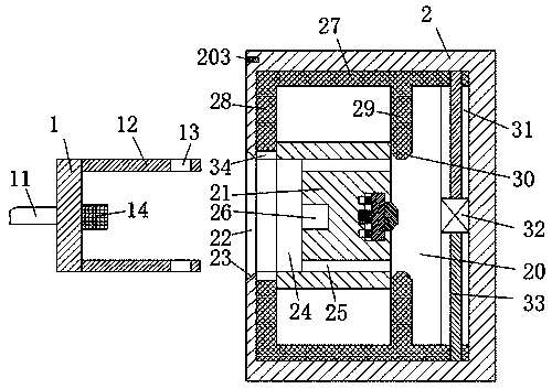
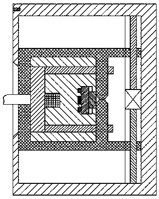
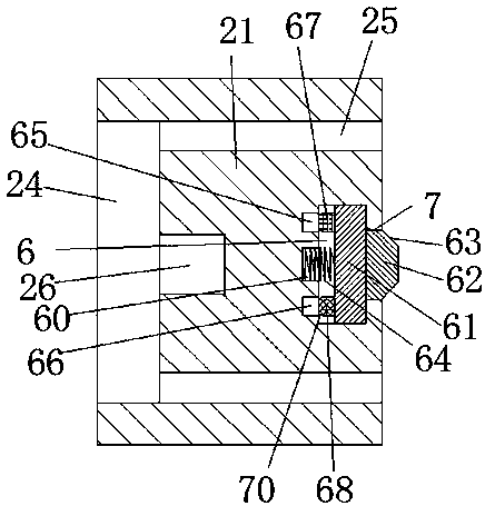
[0019] refer to Figure 1-4 The shown improved water cup includes a power transmission terminal connected to the cup body 100 through a wire 11 and a power transmission frame. The opening and closing is provided with a cup cover 103, and the power transmission terminal includes a push arm 1, and the front and rear ends of the right end surface of the push arm 1 are correspondingly provided with two insertion arms 12, and the right ends of the two insertion arms 12 are respectively A passage 13 is provided, a bumper 14 is provided at the center of the right end face of the push arm 1, the power transmission frame includes an outer frame 2, a hollo...


PUM


Abstract

The invention discloses an improved water cup, which comprises a power transmission end socket and a power transmission frame connected with a cup body by means of lead wires, wherein a handle is fixedly mounted on the left end surface of the cup body, a cup opening is formed in the right end surface, and a cup lid is arranged on the upper end surface in an openable and closeable manner; the powertransmission end socket comprises a push arm; two inserting arms are correspondingly arranged on the front and rear ends of the right end surface of the push arm; passing-through openings are formedin the right ends of the two inserting arms respectively; a collision block is arranged in the center of the right end surface of the push arm; the power transmission frame comprises an outer frame; ahollow groove is formed in the outer frame; and an inlet cavity communicated with the hollow groove is formed in the central position of the left end surface of the outer frame. The whole improved water cup can complete the power-off and power-on of the collision block through operation of one driver, namely, the power-off and power-on of the cup body can be completed through operation of one driver, the operation is easy and convenient, the power supply stability is good, the running is safe and reliable, and the cooperative operation of the collision block and a power transmission groove issimple and convenient.

Description

technical field [0001] The invention relates to the field of water cups, in particular to an improved water cup. Background technique [0002] The water cup is a commonly used appliance in people's daily life. With the continuous advancement of science and technology, the function of the water cup is not limited to the function of storing water, but also has the function of boiling water. The traditional way of boiling water requires the power transmission terminal connected to the cup body Insert it directly into the power transmission slot of the power transmission frame and connect to the power supply. The connection between the power transmission frame and the power supply will always be in the power-on state. Although this cooperation method is more convenient to operate, the length of the wire between the power transmission terminal and the cup body is different. After the power transmission terminal is inserted into the power transmission groove, there is no other loc...

Claims


Application Information

Patent Timeline
Patent Type & Authority Applications(China)
IPC IPC(8): H01R13/639H01R13/70A47J27/21
CPCH01R13/639A47J27/21008H01R13/701
Inventor 玉明福吴忠平
Owner 玉明福
Why Eureka
Try Eureka