Roller dust remover fast and convenient to use

A dust collector and drum technology, applied in the field of dust removal, can solve problems affecting production progress, low efficiency, troublesome drum replacement, etc., to improve the speed of installation and disassembly work, improve stability and work efficiency, and quickly and automatically control solutions open effect

Inactive Publication Date: 2018-07-03
楼晓帅
View PDF0 Cites 0 Cited by
  • Summary
  • Abstract
  • Description
  • Claims
  • Application Information

AI Technical Summary

Problems solved by technology

The traditional dust removal method uses a manual hand-held dust removal roller for cleaning, which is inefficient and not in place. The cleaning effect of the adhesive roller becomes poor after being used many times and needs to be replaced. The replacement of the roller of some automatic dust collectors is troublesome, time-consuming and laborious, and affects the production progress. Moreover, the drum itself is under pressure during the rolling dust removal process, and it is easy to break away from the frame, causing trouble

Method used


Image

  • Roller dust remover fast and convenient to use
  • Roller dust remover fast and convenient to use
  • Roller dust remover fast and convenient to use

Examples


Embodiment Construction

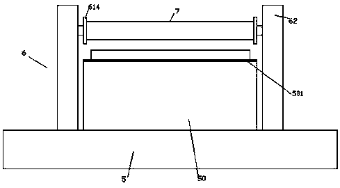
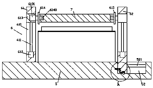
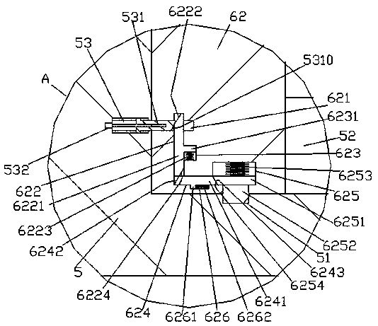
[0022] Such as Figure 1-Figure 6 As shown, a fast drum dust collector of the present invention includes a base 5 and a support device 6 arranged on the top of the base 5, and a first guide groove 52 is provided inside the top of the right side of the base 5, The inside of the first guide groove 52 is provided with a guide rod 521 extending left and right, and the support device 6 is composed of a first support frame 61 and a second support frame 62, and the first support frame 61 is fixed on The top of the left side of the base 5, the second support frame 62 is located on the right side of the base 5 and the bottom extends into the first guide groove 52, and the bottom of the second support frame 62 is provided with a The first sliding cavity 625, the first sliding cavity 625 is slidingly connected with the first sliding block 6251, and the bottom of the first sliding block 6251 is fixedly arranged to pass through the second supporting frame 62 The locking block 6252 at the ...


PUM


Abstract

The invention discloses a roller dust remover fast and convenient to use. The roller dust remover comprises a base table and an erecting device, wherein the erecting device is arranged at the top of the base table. A first guiding groove is formed into the top of the right side of the base table. A guiding rod is arranged inside the first guiding groove, wherein the guiding rod extends leftwards and rightwards. The erecting device is composed of a first erecting support and a second erecting support. The first erecting support is fixed to the top of the left side of the base table, and the second erecting support is located at the right side of the base table; and the bottom of the second erecting support extends into the first guiding groove. A first sliding cavity is formed into the bottom of the second erecting support. A first sliding block is connected into the first sliding cavity in a sliding and matched manner. A locking block is fixedly arranged at the bottom of the first sliding block, wherein the locking block penetrates the bottom of the second erecting support. A second sliding cavity is formed in the portion, at the left side of the first sliding cavity, inside the second erecting support, wherein the second sliding cavity extends upwards and downwards. A second guiding groove is formed in the inner wall of the right side of the second sliding cavity. The roller dust remover is simple in structure; rapid locking for mounting and automatic control unlocking can be achieved; the speeds of mounting work and dismounting work of a dust removal roller are increased;and a gluing roller can be ascended and descended automatically.

Description

technical field [0001] The invention relates to the field of dust removal, in particular to a fast drum dust collector. Background technique [0002] On the production line, products such as clothing, leather goods, and bedding are easily contaminated with dust, so the surface needs to be dedusted before packaging. The traditional dust removal method uses a manual hand-held dust removal roller for cleaning, which is inefficient and not in place. The cleaning effect of the adhesive roller becomes poor after being used many times and needs to be replaced. The replacement of the roller of some automatic dust collectors is troublesome, time-consuming and laborious, and affects the production progress. And the cylinder itself is under pressure and easily breaks away from the support body during the rolling dust removal process, causing trouble. Contents of the invention [0003] The technical problem to be solved by the present invention is to provide a fast drum dust collecto...

Claims


Application Information

Patent Timeline
Patent Type & Authority Applications(China)
IPC IPC(8): B08B7/00
CPCB08B7/0028
Inventor 楼晓帅叶利萍
Owner 楼晓帅
Why Eureka
Try Eureka