Eureka AIR delivers breakthrough ideas for toughest innovation challenges, trusted by R&D personnel around the world.

Novel welding device

A welding device, a new type of technology, applied in auxiliary devices, welding equipment, metal processing, etc., can solve problems such as shortened service life, potential safety hazards, and insecurity, and achieve the effects of improving safety, increasing service life, and convenient operation

Inactive Publication Date: 2018-07-03
桐乡市远邦传感器有限公司
View PDF0 Cites 0 Cited by
  • Summary
  • Abstract
  • Description
  • Claims
  • Application Information

AI Technical Summary

Problems solved by technology

[0002] The electric soldering iron is the most widely used and common welding equipment in real life. It is mainly used for welding components and wires. It is very easy to be affected by dragging, pulling, etc. and cause instability during use. When not in use, it is more cumbersome and difficult to put away the power supply line, and the power supply line is exposed to the outside for a long time, which is easy to cause wear and tear, shortening the service life. At the same time, it is not safe to insert manually during use, and it is very easy to induce electric shock due to wet and slippery hands, and there is a great potential safety hazard.

Method used


Image

  • Novel welding device
  • Novel welding device
  • Novel welding device

Examples


Embodiment Construction

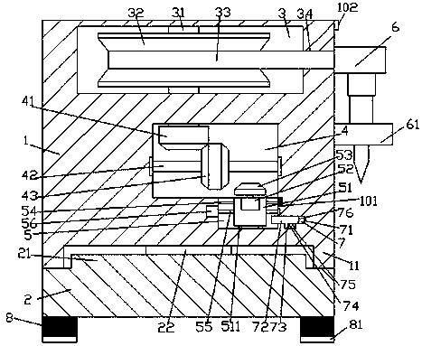
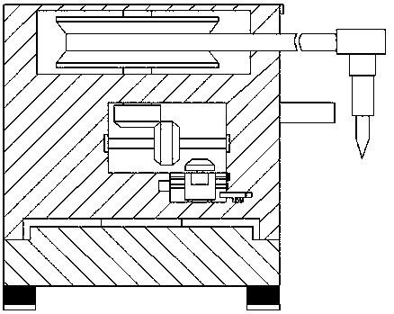
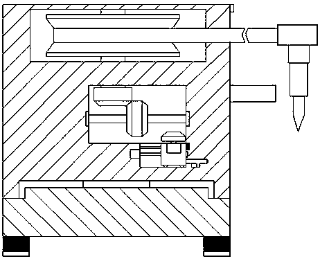
[0022] Such as Figure 1-Figure 6 As shown, a new type of welding device of the present invention includes a base body 2 and a body 1 installed above the base body 2. The body 1 is provided with a first cavity 3, and the right side of the first cavity 3 is provided with Through the groove 34 passing through the outer wall of the body 1 and communicating with the first cavity 3, the body 1 at the bottom of the first cavity 3 is provided with a second cavity 4, and the second cavity The inner bottom of the right side of the chamber 4 is provided with a first sliding groove 5, and the inner wall of the right side of the first sliding groove 5 is provided with a second sliding groove 7, and the bottom of the second sliding groove 7 is provided with a guide groove 75, the first revolving pin shaft 31 extending downward and entering the second receptacle 4 is provided in the first cavity 3, the first revolving pin shaft in the first cavity 3 The outer surface of 31 is fixed with a ...


PUM


Abstract

The invention discloses a novel welding device which comprises a seat body and a machine body arranged on the seat body; a first containing cavity is formed in the machine body; a penetrable groove which penetrates through the outer side wall of the machine body and communicates with the first containing cavity is formed in the right side of the first containing cavity; a second containing cavityis formed in the part, at the bottom of the first containing cavity, of the machine body; a first sliding groove is formed in the bottom in the right side of the second containing cavity; a second sliding groove is formed in the inner wall of the right side of the first sliding groove; a guide moving groove is formed in the bottom of the second sliding groove; a first rotary pin shaft which extends downwards and enters into the second containing cavity is arranged in the first containing cavity; a winding disc is fixedly arranged on the part, in the first containing cavity, of the outer surface of the first rotary pin shaft; a wire is arranged on the winding disc; the end face of the right side of the wire penetrates through the penetrable groove and threads out of the outer side wall of the machine body, and the tail of the right side of the wire is fixedly connected with a welding part; a clamping ring is arranged on the part, on the lower side of the welding part, of the outer sidewall of the machine body; and the bottom of the welding part penetrates through the clamping ring and is connected with the clamping ring in a clamping fit manner. The novel welding device is simple in structure and convenient to operate, automatic power supply and power-off work can be realized, the winding is relatively simple and convenient, the safety in use is improved, and the service life is prolonged.

Description

technical field [0001] The invention relates to the field of welding technology, in particular to a novel welding device. Background technique [0002] The electric soldering iron is the most widely used and common welding equipment in real life. It is mainly used for welding components and wires. It is very easy to be affected by dragging, pulling, etc. and cause instability during use. When not in use, it is more cumbersome and difficult to put away the power supply line, and the power supply line is exposed to the outside for a long time, which is easy to cause wear and tear, shortening the service life. At the same time, it is relatively unsafe to manually insert and connect during use, and it is very easy to induce electric shock due to wet and slippery hands, and there is a great potential safety hazard. Contents of the invention [0003] The technical problem to be solved by the present invention is to provide a new type of welding device, which can solve the above...

Claims


Application Information

Patent Timeline
Patent Type & Authority Applications(China)
IPC IPC(8): B23K3/00B23K3/08
CPCB23K3/00B23K3/08
Inventor 卫杰
Owner 桐乡市远邦传感器有限公司
Why Eureka
Eureka Blog
Learn More