Eureka AIR delivers breakthrough ideas for toughest innovation challenges, trusted by R&D personnel around the world.

Convenient-to-maintain bridge equipment

A technology that facilitates maintenance and bridges. It is applied to devices with bendable leads, parts of connecting devices, and connecting/disconnecting of connecting devices. It can solve the problems of difficult implementation of maintenance work, inability to connect with power supply, hidden dangers, etc., and achieve structural Simple, strong protective performance, and the effect of preventing electric shock accidents

Inactive Publication Date: 2018-07-03
朱晓凤
View PDF0 Cites 0 Cited by
  • Summary
  • Abstract
  • Description
  • Claims
  • Application Information

AI Technical Summary

Problems solved by technology

[0002] Electrified maintenance equipment is often used in the bridge maintenance process. However, in some bridge constructions, there are fewer preset power supply seats and they are all fixed, which makes some bridge maintenance equipment in maintenance because the maintenance parts are far from the power supply seats The lack of power supply connection makes it difficult to implement maintenance work. At the same time, the power supply part of the existing middle bridge is generally set outside, and it is still charged when it is not plugged in. There is a possibility of inducing electric shock when accidentally touched by humans, and there is a greater safety. Hidden danger

Method used


Image

  • Convenient-to-maintain bridge equipment
  • Convenient-to-maintain bridge equipment
  • Convenient-to-maintain bridge equipment

Examples


Embodiment Construction

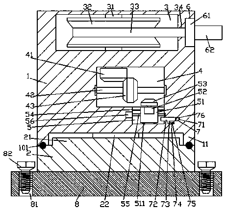
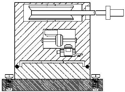
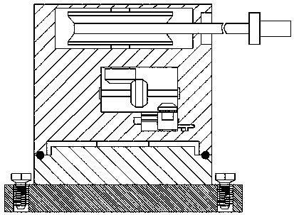
[0022] like Figure 1-Figure 6 As shown, the maintenance-friendly bridge equipment of the present invention includes a steering part 2 and a base body 1 installed above the steering part 2. The base body 1 is provided with a first container 3, and the first container 3 is right The outer wall of the substrate 1 on the side is provided with a settling groove 6, and a communication groove 34 is provided between the settling groove 6 and the first container 3, and the substrate 1 at the bottom of the first container 3 There is a second container 4 inside, the bottom of the right side of the second container 4 is provided with a first push groove 5, and the inner wall of the right side of the first push groove 5 is provided with a second push groove 7. The bottom of the second push groove 7 is provided with a groove 75, and the first steering shaft 31 extending downward and protruding into the second groove 4 is arranged in the first container 3, and the first steering shaft 31 is...


PUM


Abstract

The invention discloses convenient-to-maintain bridge equipment. The convenient-to-maintain bridge equipment comprises a steering part and a base body, wherein the base body is arranged above the steering part; a first accommodating groove is formed in the base body; a placement groove is formed in an outer side wall of the base body at a right side of the first accommodating groove; a through groove is formed between the placement groove and the first accommodating groove; a second accommodating groove is formed in the base body at the bottom of the first accommodating groove; a first push groove is formed in the bottom of a right side of the second accommodating groove; a second push groove is formed in an inner wall of a right side of the first push groove; a groove is formed in the bottom of the second push groove; a first steering shaft is arranged in the first accommodating groove, extends downwards and is stretched into the second accommodating groove; a winding disc is fixedlyarranged on an outer surface of the first steering shaft in the first accommodating groove; a cable is arranged on the winding disc; an end surface of a right side of the cable penetrates through thethrough groove and is stretched into the placement groove; a buckle block is arranged in the placement groove and is fixedly connected with a tail end of a right side of the cable; a socket is arranged at a right side of the buckle block; and multiple groups of power transmission holes are formed in a top surface of the socket. The convenient-to-maintain bridge equipment is simple in structure andhigh in protection performance and is convenient to operate, operation of power supply at different distances can be met, operation of power supply and power failure can be automatically achieved, the safety is improved, an electric shock accident is prevented, and the bridge equipment is suitably used for promotion and application in a bridge.

Description

technical field [0001] The invention relates to the technical field of bridge equipment, in particular to convenient maintenance bridge equipment. Background technique [0002] Electrified maintenance equipment is often used in the bridge maintenance process. However, in some bridge constructions, there are fewer preset power supply seats and they are all fixed. The lack of power supply connection makes it difficult to implement maintenance work. At the same time, the power supply part of the existing middle bridge is generally set outside, and it is still charged when it is not plugged in. There is a possibility of inducing electric shock if it is accidentally touched by humans, and there is a greater safety. Hidden danger. Contents of the invention [0003] The technical problem to be solved by the present invention is to provide a convenient maintenance bridge device, which can solve the above-mentioned problems in the prior art. [0004] The present invention is achi...

Claims


Application Information

Patent Timeline
Patent Type & Authority Applications(China)
IPC IPC(8): H01R13/72H01R35/00H01R13/642H01R43/26
CPCH01R13/72H01R13/642H01R35/00H01R43/26
Inventor 朱晓凤
Owner 朱晓凤
Why Eureka
Eureka Blog
Learn More