Welding device facilitating welding operation

A welding device and operation technology, applied in the direction of auxiliary devices, welding equipment, auxiliary welding equipment, etc., can solve the problems of easy damage to the welding table, unadjustable distance, waste of cost, etc., to prevent the center of gravity from shifting, save replacement costs, The effect of simple disassembly steps

Inactive Publication Date: 2018-07-03
张建松
View PDF0 Cites 4 Cited by
  • Summary
  • Abstract
  • Description
  • Claims
  • Application Information

AI Technical Summary

Problems solved by technology

[0002] When workers perform welding operations, they usually place the welding machine or the required welding workpiece on the workbench, so as to facilitate the welding operation. The existing welding workbench usually has a simple design and structure, and the length of its legs cannot be adjusted up and down, and the welding workbench The welding table is fixedly connected with the feet. After long-term welding operation, the welding table is most likely to be damaged, so the welding table needs to be replaced. The existing welding table is usually unable to be replaced, and the entire welding table needs to be replaced, which is a waste of cost. Moreover, the distance between each leg of the existing welding workbench cannot be adjusted, so that the size of the table top of the welding workbench cannot be adjusted, so there are certain defects in the existing welding workbench

Method used


Image

  • Welding device facilitating welding operation
  • Welding device facilitating welding operation
  • Welding device facilitating welding operation

Examples


Embodiment Construction

[0022] All features disclosed in this specification, or steps in all methods or processes disclosed, may be combined in any manner, except for mutually exclusive features and / or steps.

[0023] Any feature disclosed in this specification (including any appended claims, abstract and drawings), unless expressly stated otherwise, may be replaced by alternative features which are equivalent or serve a similar purpose. That is, unless expressly stated otherwise, each feature is one example only of a series of equivalent or similar features.

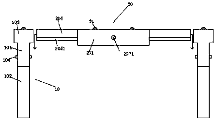
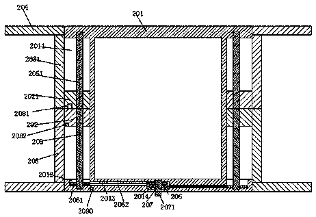
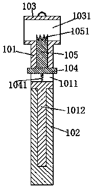
[0024] Such as Figure 1-6 As shown, a welding device of the present invention that facilitates welding operations includes a top seat 20, a leg 10, and a welding table 30. The top seat 20 includes a main base body 201, and the left and right sides of the main base body 201 are symmetrically arranged with front and rear Extended sliding groove 2011 with the mouth facing outwards, the front end of the main base body 201 is provided with a midd...


PUM


Abstract

The invention relates to a welding device facilitating welding operation. The welding device comprises a top base, landing legs and a welding table top, the top base comprises a main base body, sliding grooves which extend front and back and are provided with outward opening parts are symmetrically arranged in the main base body in a left-and-right symmetrical manner, middle rotating grooves located at the middle portions of the left and right sides are arranged in the front end of the main base body, first belt wheels are rotationally installed in the middle rotating grooves through rotatingshafts, side edge rotating grooves are arranged in the front ends of the sliding grooves, conveying grooves which communicate to each other are arranged between the side edge rotating grooves and themiddle rotating grooves, a front sliding block and a back sliding block which are installed in a front-and-back sliding manner are arranged in the sliding grooves, a front screw rod and a back screw rod which are installed in a spiral fit manner are arranged in the front sliding block and the back sliding block, the front screw rod and the back screw rod are fixedly connected, second belt wheels are installed on the side edge rotating grooves and are fixedly connected with the front screw rod, the first belt wheels and the second belt wheels are provided with belts, a front connecting rod extending forwards is fixedly arranged on the outer side end of the front sliding block, and a back connecting rod extending backwards is fixedly arranged on the outer side end of the back sliding block.

Description

technical field [0001] The invention relates to the field of welding, in particular to a welding device that facilitates welding operations. Background technique [0002] When workers perform welding operations, they usually place the welding machine or the required welding workpiece on the workbench, so as to facilitate the welding operation. The existing welding workbench usually has a simple design and structure, and the length of its legs cannot be adjusted up and down, and the welding workbench The welding table is fixedly connected with the feet. After long-term welding operation, the welding table is most likely to be damaged, so the welding table needs to be replaced. The existing welding table is usually unable to be replaced, and the entire welding table needs to be replaced, which is a waste of cost. Moreover, the distance between each leg of the existing welding workbench cannot be adjusted, so that the size of the table top of the welding workbench cannot be adj...

Claims


Application Information

Patent Timeline
Patent Type & Authority Applications(China)
IPC IPC(8): B23K37/04B23K37/00
CPCB23K37/0461B23K37/00
Inventor 张建松郭超杰
Owner 张建松
Why Eureka
Try Eureka